Wrapper assembly

a technology of wrapping wire and assembly, which is applied in the field of wrapping wire assembly, can solve the problems of complicated design and operation of wire wrapping machines, limited use of wire wrapping machines to immovable fixtures or devices, and high complexity of conventional wire wrapping machines in terms of parts and operation, so as to reduce the number of components in the assembly and achieve the effect of compactness and reducing the number of components

Active Publication Date: 2014-07-22
BRADY WORLDWIDE INC
View PDF17 Cites 8 Cited by
  • Summary
  • Abstract
  • Description
  • Claims
  • Application Information

AI Technical Summary

Benefits of technology

[0007]An assembly is disclosed having a structure and a style of operation that differs from conventional wire wrapping mechanisms. This new structure can be much more compact and reduces the number of components in the assembly without impairing functionality. Accordingly, such an assembly is well-suited for use in a portable device.
[0011]Each of the pair of supports or discs may include a notch that generally extends from a center of the support or disc to a periphery of the support or disc. Likewise, the yoke(s) may include a corresponding notch. Together, these notches accommodate for the insertion or positioning of a wire or other object along the central rotational axis of the rotatable subassembly and in between the rollers. When the rotatable subassembly is placed within a frame, the frame also may include at least one opening that aligns with the notches in at least one rotation position of the rotatable subassembly in the frame. In this position, a section of wire or another item may be received into the rotatable subassembly by radially inserting a section of the wire into the notches of supports and yokes and opening in the frame. Accordingly, the wire does not need to be axially threaded through the rotatable subassembly.

Problems solved by technology

Because the wire or object to be wrapped may take on various shapes or sizes, this can complicate the design and operation of such wire wrappers.
Accordingly, these conventional wire wrapping machines are very complex in terms of parts and operation.
Frequently, this means the use of such wire wrappers are limited to immovable fixtures or devices that are not well-adapted for portable use.

Method used


Image

  • Wrapper assembly
  • Wrapper assembly
  • Wrapper assembly

Examples


Embodiment Construction

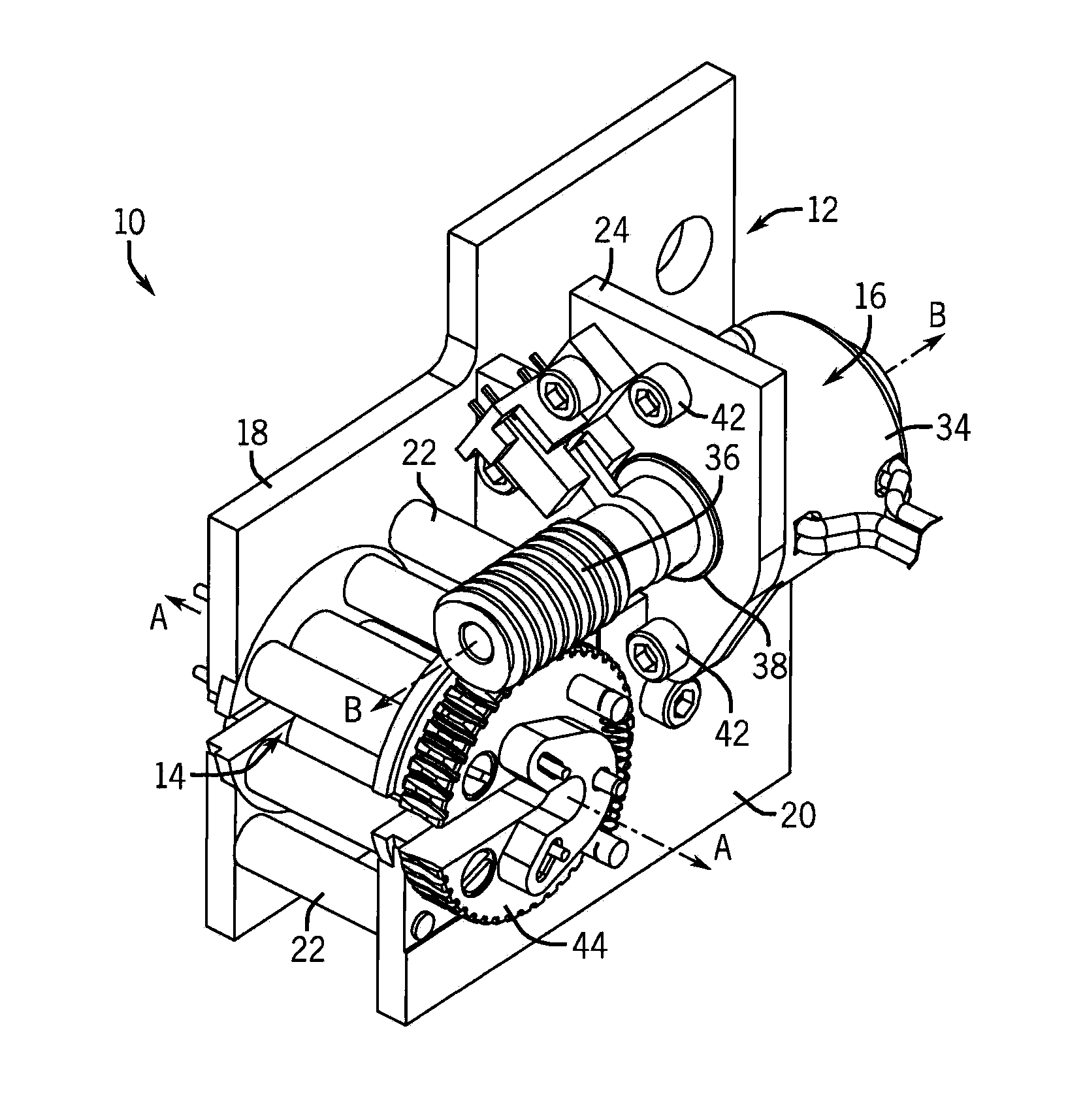
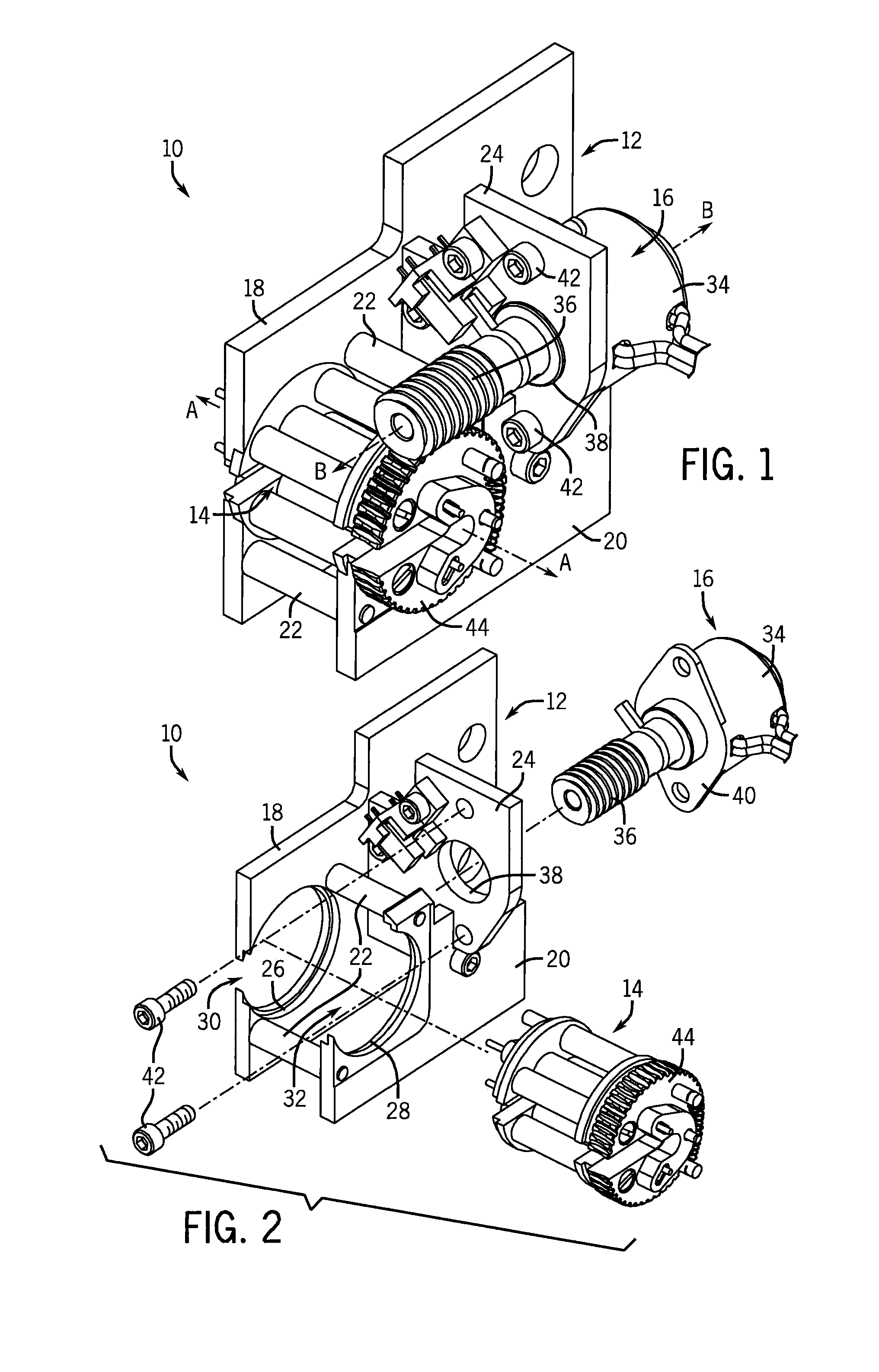
[0030]Referring first to FIGS. 1 and 2, a wrapper assembly 10 for capturing a wire and then wrapping a label around the wire is illustrated. In the form shown, the wrapper assembly 10 is part of a fixture. However, this is just one exemplary embodiment and the wrapper assembly 10 could be part of a larger device such as, for example, a printer or a portable device.

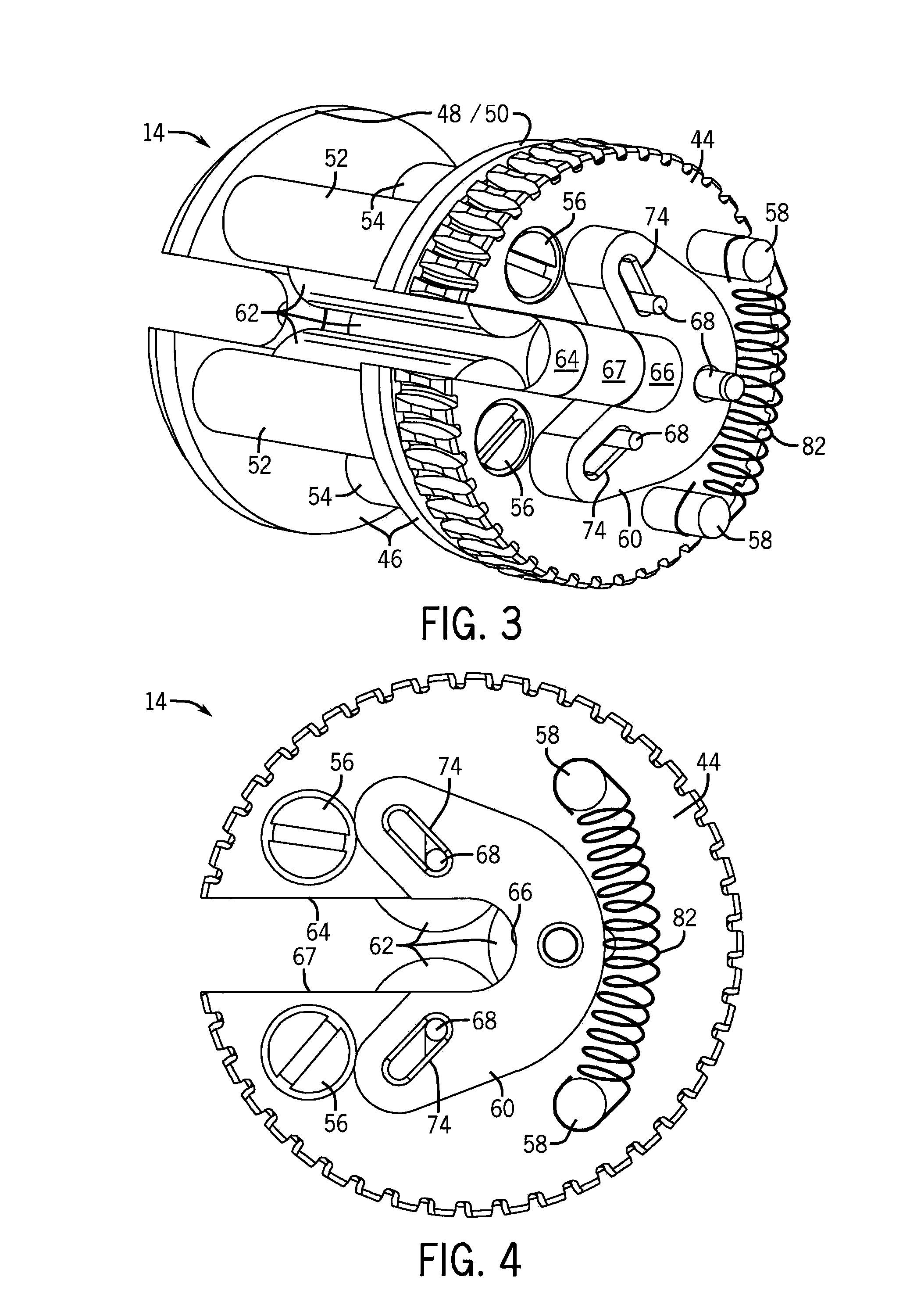
[0031]To summarize the general construction and operation of the wrapper assembly 10, the wrapper assembly 10 includes a frame 12 that supports a rotatable subassembly 14. The rotatable subassembly 14 is configured to receive a wire or another slender object. When the wire or other object is received in the rotatable subassembly 14, then the rotatable subassembly 14 may be rotated about an axis of rotation A-A by a driving mechanism 16, which is also supported by the frame 12, and a label or other item may be affixed to the wire.

[0032]As indicated above, the frame 12 supports the other components in the wrapper assembly 10...


PUM

PropertyMeasurementUnit
rotationaaaaaaaaaa
angleaaaaaaaaaa
circumferenceaaaaaaaaaa

Abstract

A wrapper assembly is disclosed that can be used, for example, to wrap a label around a wire. In the wrapper assembly, a pair of supports are spaced apart from one another and a plurality of rollers are disposed there between. The wrapper assembly further includes at least one yoke. Both the pair of supports and the yoke have positioning slots formed therein that support the rollers. By moving the yoke or yokes relative to the supports, the positioning slots in the yoke or yokes shifts relative to the positioning slots in the supports and thereby adjusting the positions of rollers relative to one another.

Description

CROSS-REFERENCE TO RELATED APPLICATIONS[0001]Not applicable.STATEMENT OF FEDERALLY SPONSORED RESEARCH OR DEVELOPMENT[0002]Not applicable.BACKGROUND[0003]This disclosure relates to an assembly for gripping and rotating objects. In particular, this disclosure relates to a wrapper assembly that facilitates the wrapping of a label around a slender object such as, for example, a printed label around a wire.[0004]Various devices and machines have been developed for the application of labels to wires and other slender objects. Typically, such machines grasp two ends of a section of the wire and pull this section of wire taut. Once the wire is pulled taut, a label applicator or platform orbits around the taut section of wire to apply the label to the wire. This label applicator must be capable of orbiting around the wire while applying an appropriate amount and type of pressure between the label applicator and the wire. Because the wire or object to be wrapped may take on various shapes or ...

Claims


Application Information

Patent Timeline
Patent Type & Authority Patents(United States)
IPC IPC(8): B65B13/04B65B13/10B65C3/02B65C3/04B65C9/32B65H81/02
CPCB65C3/02B65C9/32
Inventor WITKIEWICZ, ADAM
Owner BRADY WORLDWIDE INC
Why Eureka
Try Eureka