
Braking device

a technology of braking device and braking plate, which is applied in the direction of engineering emergency devices, mechanical devices, manufacturing tools, etc., can solve the problems of reducing the precision of the hydrostatic bearing module, operator injury or even death, and affecting the accuracy of the machine tool. , to achieve the effect of reducing the precision of the machine tool

Active Publication Date: 2014-07-22
IND TECH RES INST
View PDF43 Cites 2 Cited by
  • Summary
  • Abstract
  • Description
  • Claims
  • Application Information

AI Technical Summary

Benefits of technology

The present invention is a braking device that prevents a decrease in the precision of a machine tool caused by continuous operation in case of power off. The braking device reduces the external force generated by hydraulic pressure and allows the reset member to butt the piston. The clamping block shifts to the braking position, achieving a power-off braking effect.

Problems solved by technology

As such, damage of precise transmission elements or failure of workpieces in the machine tool may occur, and operators may be hurt or even dead due to the damage of the machine tool.
In addition, the precision of the hydrostatic bearing module may be affected by the power cut, leading to a decreased precision of the hydrostatic bearing module.

Method used


Image

  • Braking device
  • Braking device
  • Braking device

Examples


Embodiment Construction

[0019]In view of the issue in the related art, a safety device needs to be installed on the machine tool, so that the safety device of the machine tool can help to stop the rotating working platform in case of power cut, so as to prolong the service life of the hydrostatic bearing and improve the safety of the operator in work.

[0020]Accordingly, the present disclosure is a braking device, which can stop a machine tool while power cut occurs, so as to prolong the service life of a hydrostatic bearing in the machine tool and improve the safety of the operator in work.

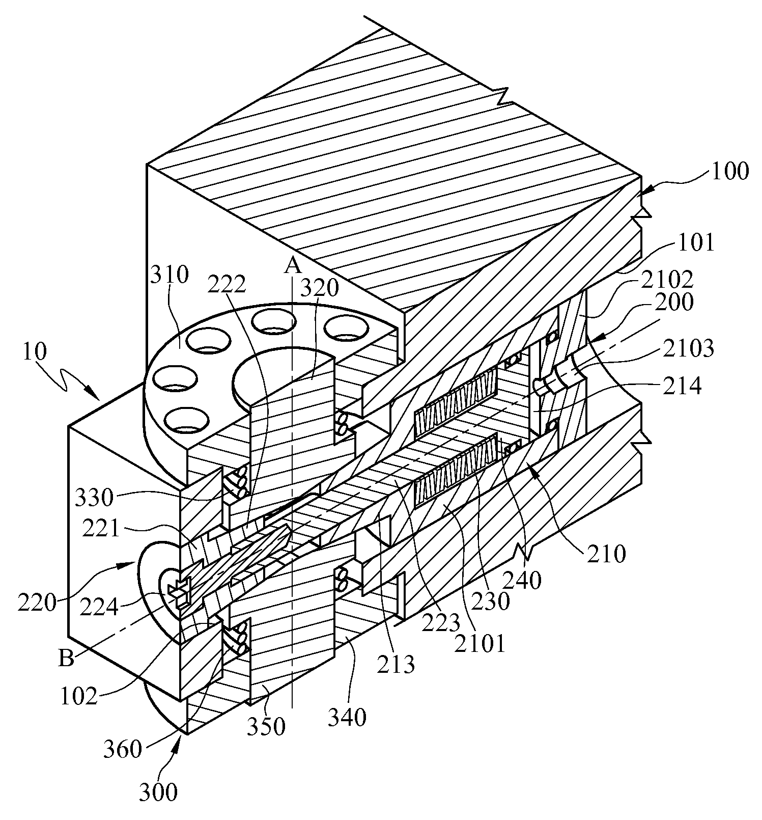
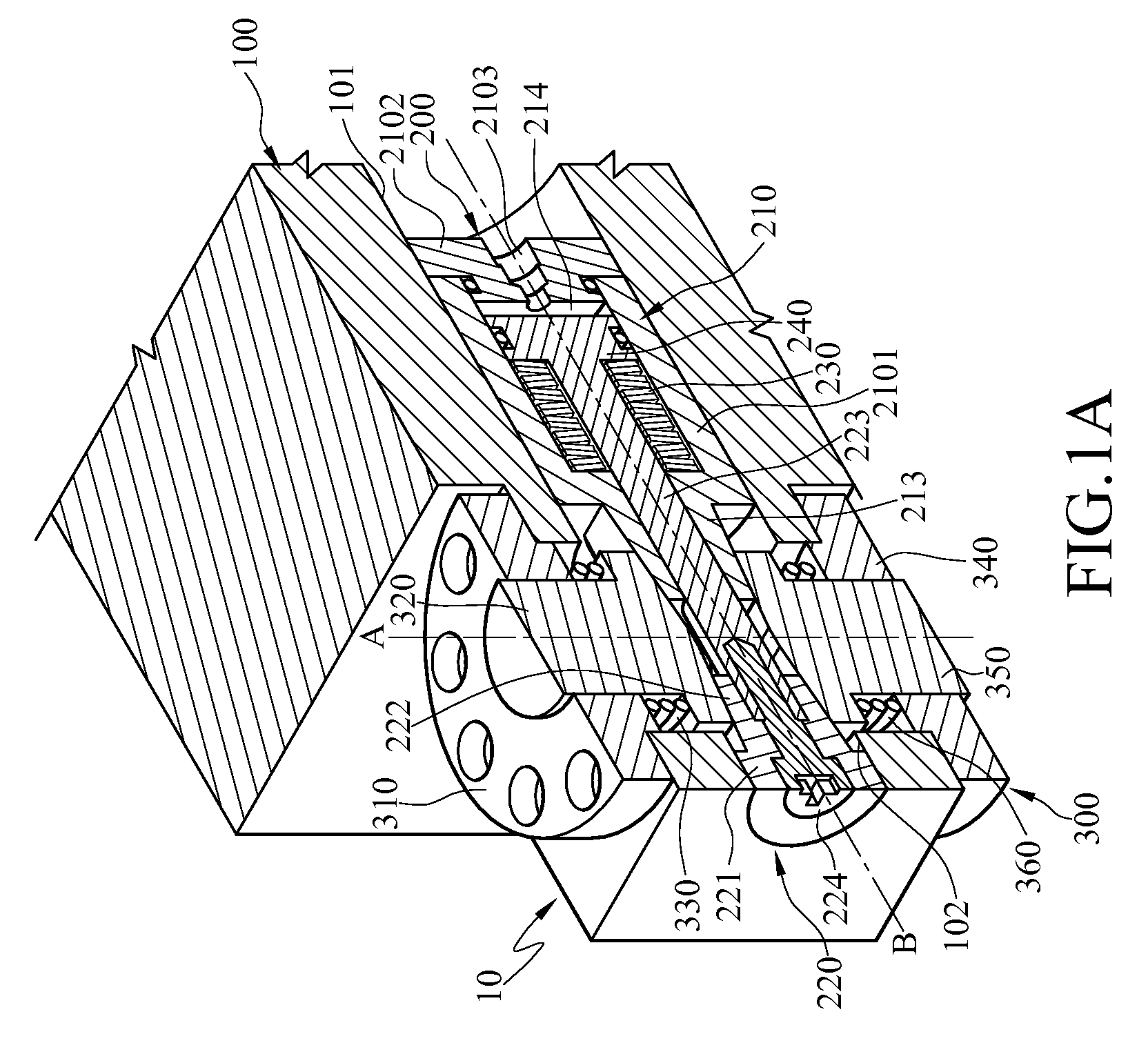
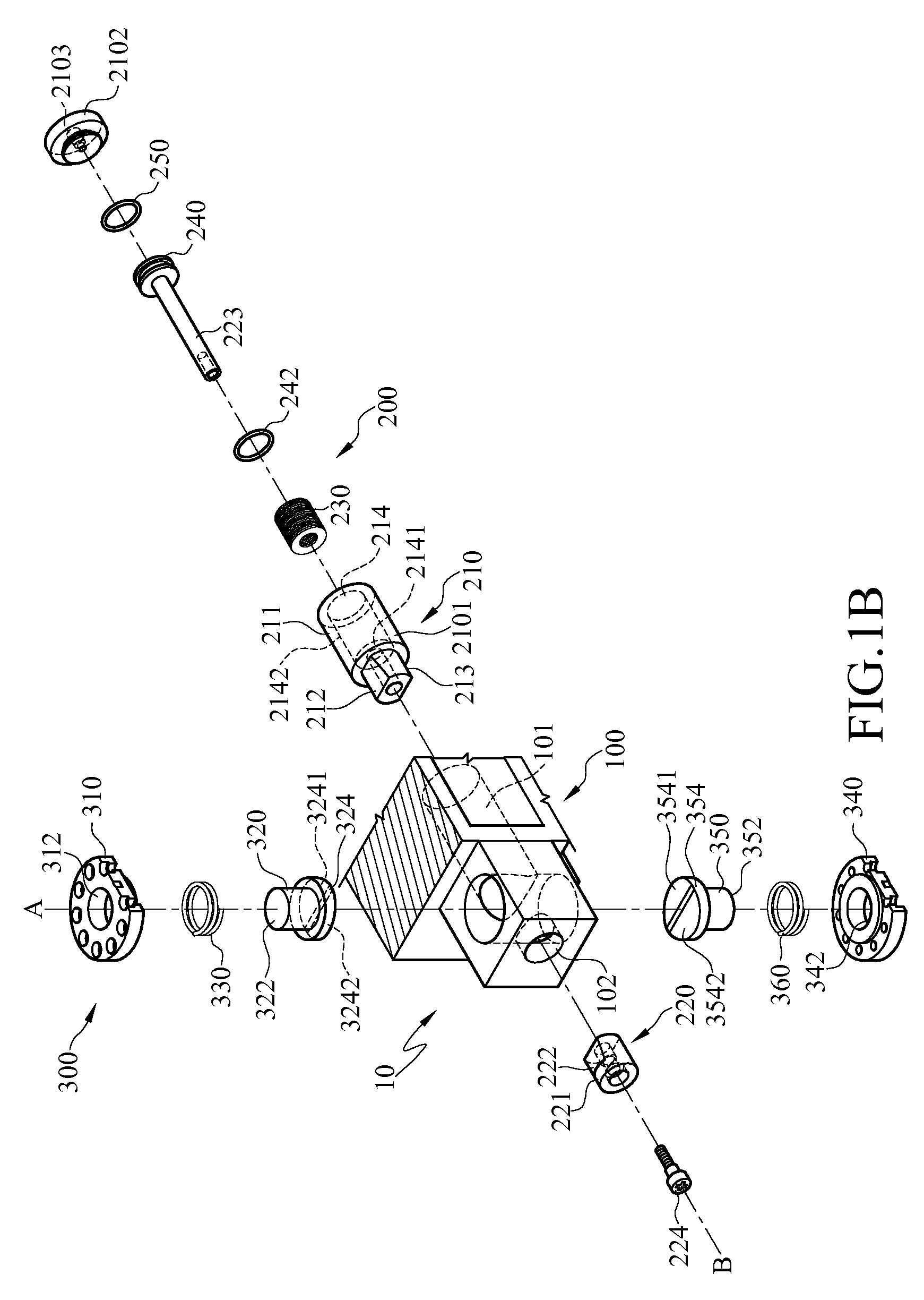
[0021]FIG. 1A is a structural sectional view of a braking device according to an embodiment of the present disclosure, and FIG. 1B is an exploded structural sectional view of a braking device according to an embodiment of the present disclosure.

[0022]Referring to FIGS. 1A and 1B, in this embodiment, the braking device 10 comprises a base 100, a braking component 300, and a driving component 200. The base 100 has a first s...


PUM


Abstract

A braking device includes a base, a braking component, and a driving component including a reset member. The braking component has a clamping block. The driving component includes a movable member, a chamber therein and a first butting portion. The movable member passes through the driving member. One end of the movable member has a piston accommodated in the chamber, and the other end of the movable member has a second butting portion. The reset member is disposed in the chamber. The piston butts the reset member under an external force, and the first butting portion and the second butting portion are kept away from each other, and when the external force vanishes, the reset member butts the piston, and the first butting portion and the second butting portion are kept close to each other so as to achieve a braking effect.

Description

CROSS-REFERENCE TO RELATED APPLICATIONS[0001]This non-provisional application claims priority under 35 U.S.C. §119(a) on Patent Application No(s). 100137574 filed in Taiwan, R.O.C. on Oct. 17, 2011, the entire contents of which are hereby incorporated by reference.BACKGROUND[0002]1. Technical Field[0003]The present disclosure relates to a braking device, and in particular, to a braking device capable of reacting to power cut.[0004]2. Related Art[0005]Recently, with the rapid change of technology and widespread information, various automatic machine tools of high precision come out successively. All the types of casing appearances and even plastic injection molds can be machined by the automatic machine tool, so as to obtain a product size with high precision. Generally, a machining platform of the automatic machine tool is able to shift linearly or rotate relative to a base of the automatic machine tool, so as to meet various machining requirements. Therefore, high-precision linear ...

Claims


Application Information

Patent Timeline
Patent Type & Authority Patents(United States)
IPC IPC(8): F16D55/08
CPCF16D63/008B23Q11/0092F16D2121/04F16P7/00
Inventor CHEN, SHANG-TECHEN, KUAN-WENLI, KUNG-YINGHSIAO, HSI-HUNG
Owner IND TECH RES INST
Learn More