Eureka AIR delivers breakthrough ideas for toughest innovation challenges, trusted by R&D personnel around the world.

Measuring endoscope apparatus

a technology of measuring endoscope and measuring endoscope, which is applied in the field of measuring endoscope apparatus, can solve the problems of reducing the accuracy of measuring precision, affecting the accuracy of measuring endoscope, and requiring complicated processing sequences for calibration, so as to achieve the effect of reducing the accuracy

Inactive Publication Date: 2005-05-10
EVIDENT CORP
View PDF7 Cites 9 Cited by
  • Summary
  • Abstract
  • Description
  • Claims
  • Application Information

AI Technical Summary

Benefits of technology

[0016]The present invention is devised in consideration of the above-mentioned problems. It is an object of the present invention to provide a measuring endoscope apparatus which can prevent the measuring that might cause the decrease of precision due to the change in positional relationship between an optical system of an optical adaptor and an image pick-up device, in the case of measurement using a stored calibration result.

Problems solved by technology

In this case, the difference between the positional relationship between the image pick-up device and the optical system to which the optical adaptor is attached and the previously-performed calibration result might cause the decrease in measuring precision.
However, the calibration on every attachment of the optical adaptor requires complicated processing sequence.
A processing capacity of microprocessors used for the current measuring endoscope takes a long time for the calibration.
However, the measurement might be implemented in a state in which the optical adaptor mismatches the data on the measurement environment stored as the calibration result because only the optical adaptor is replaced and the data on the measurement environment is not selected.
This might decrease the measuring precision.

Method used


Image

  • Measuring endoscope apparatus
  • Measuring endoscope apparatus
  • Measuring endoscope apparatus

Examples


first embodiment

(First Embodiment)

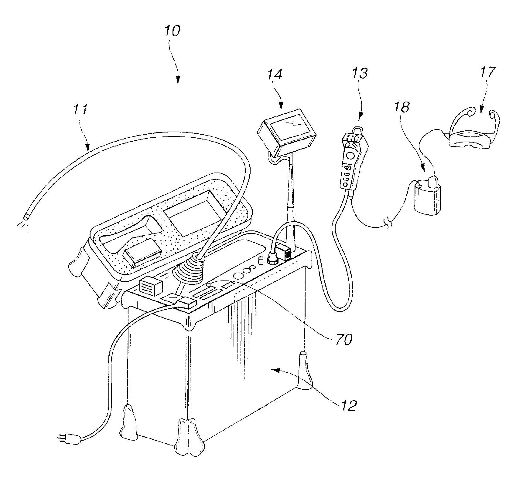
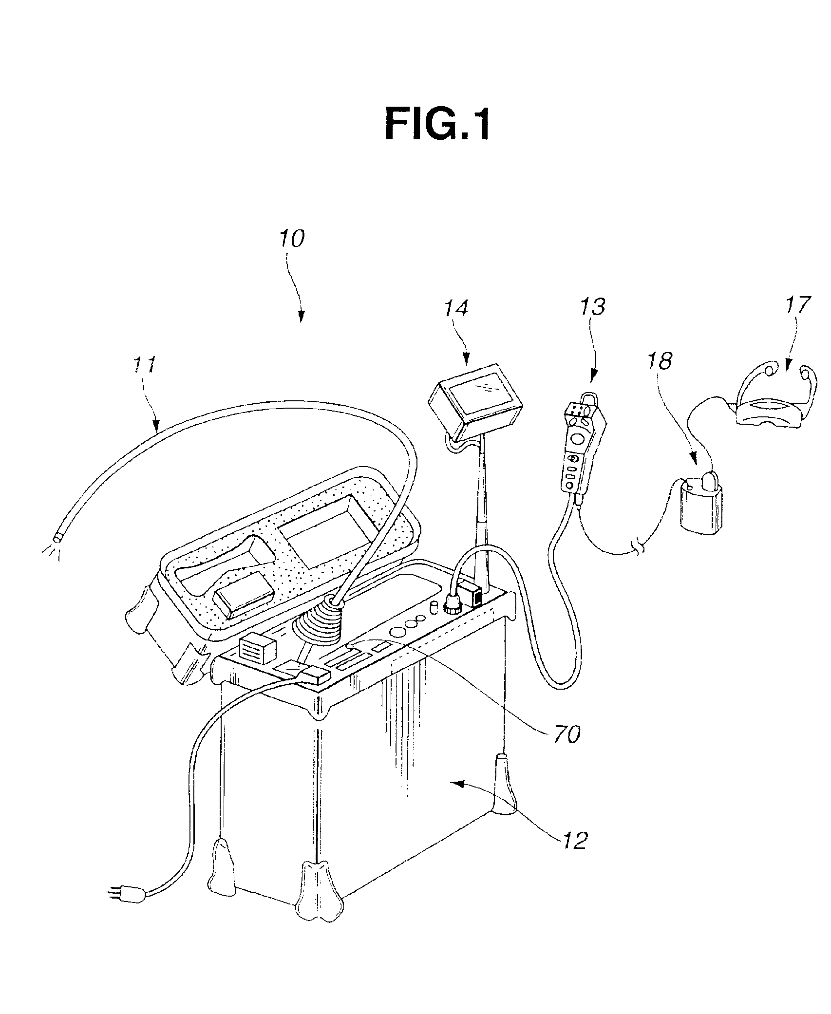
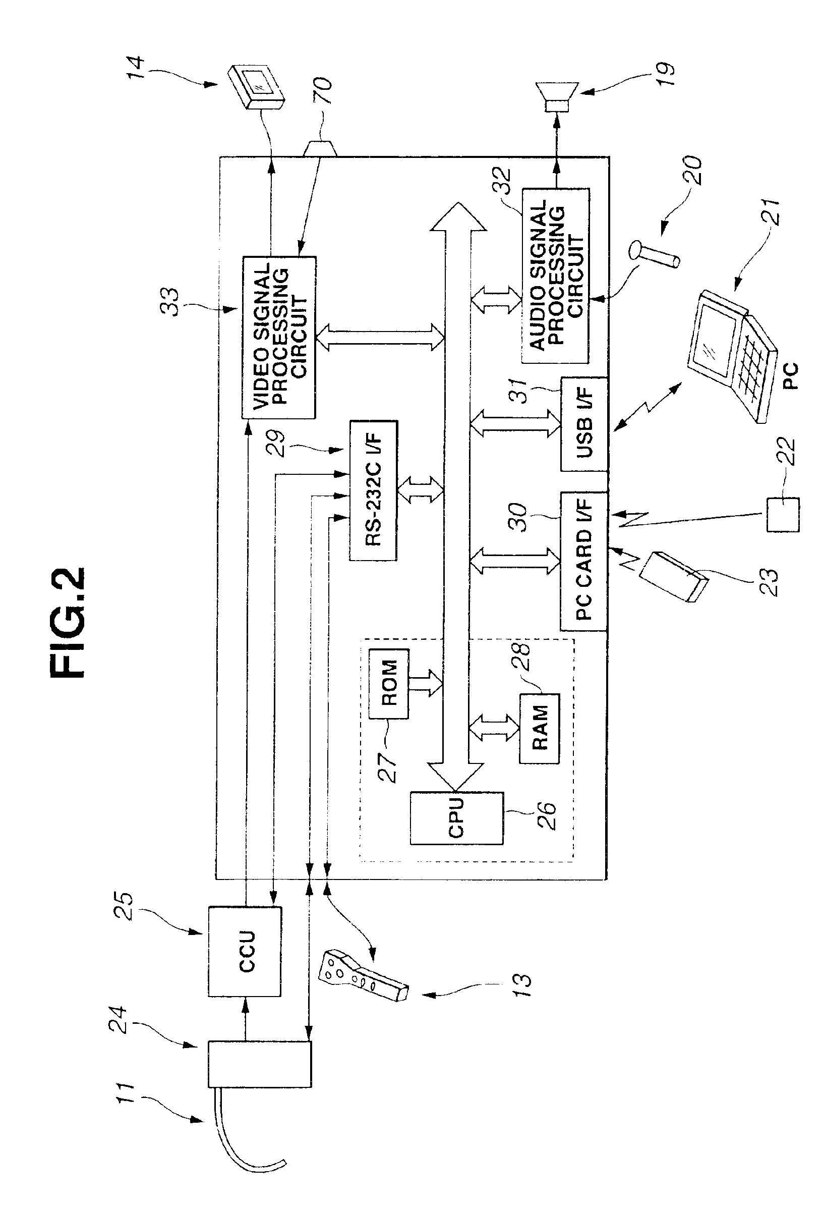
[0040]FIGS. 1 to 14 are diagrams for explaining a measuring endoscope apparatus according to a first embodiment of the present invention. FIG. 1 is a perspective view showing the system structure of the measuring endoscope apparatus according to the first embodiment of the present invention, FIG. 2 is a block diagram showing the structure of circuitries in the measuring endoscope apparatus in FIG. 1, FIG. 3 is a block diagram showing the structure of the processing of a CPU in the measuring endoscope apparatus in FIG. 2, FIG. 4 is a perspective view showing the structure of the tip of an endoscope, to which a stereo optical adaptor is attached, FIG. 5 is a sectional view of a V—V cut-plane in FIG. 4, FIG. 6 is an explanatory diagram showing an endoscopic image in the case of attaching the stereo optical adaptor, FIG. 7 is a perspective view showing the structure of a remote controller, FIG. 8 is a perspective view showing the structure of the tip of the endoscope, ...


PUM


Abstract

A processing unit includes a positional relationship information extracting unit for extracting first information on a positional relationship of an optical adaptor by performing the image processing of a signal transmitted from an image pick-up unit upon capturing the image of a predetermined subject, a storing device for storing the first information on the positional relationship, a comparing and determining unit for comparing the first information on the positional relationship stored in the storing device with second information on the positional relationship which is extracted again by the extracting unit when replacing the optical adaptor by using the tip of an endoscope insertion portion, and a notifying unit for notifying a determination result based on determination information from the comparing and determining unit. Thus, it is possible to prevent the execution of measuring from deteriorating the precision by the change in positional relationship between an optical system of the optical adaptor and an image pick-up device.

Description

[0001]This application claims benefit of Japanese Application No. 2001-162869 filed on May 30, 2001, the contents of which are incorporated by this reference.BACKGROUND OF THE INVENTION[0002]1. Field of the Invention[0003]The present invention relates to a measuring endoscope apparatus and, more particularly, to a measuring endoscope apparatus in which a plurality of optical adaptors can be replaced to use at the tip of an insertion portion of the endoscope.[0004]2. Description of the Related Art[0005]In general, the detailed examination of a subject by using an endoscope requires the measuring of the position of the subject. To satisfy this request, conventionally, various measuring apparatuses using the endoscope are proposed.[0006]For example, a proposal disclosed in Japanese Unexamined Patent Application Publication No. 10-248806 shows a measuring endoscope apparatus for stereo measuring.[0007]Further, a proposal disclosed in Japanese Patent Application No. 2000-101122 by the ap...

Claims


Application Information

Patent Timeline
Patent Type & Authority Patents(United States)
IPC IPC(8): A61B1/00A61B1/04G02B23/24G02B23/26H04N7/18H04N13/02H04N25/00
CPCA61B1/00041A61B1/00096A61B1/04A61B1/00193A61B1/00101A61B1/0004
Inventor OGAWA, KIYOTOMI
Owner EVIDENT CORP
Why Eureka
Eureka Blog
Learn More