Powered surgical tool with an isolation circuit connected between the tool power terminals and the memory internal to the tool

a technology of isolation circuit and power supply terminal, which is applied in the field of surgical tool system, can solve problems such as incorrect system setup, tool malfunction, and limitations of known systems

Active Publication Date: 2014-07-22
STRYKER CORP
View PDF26 Cites 1272 Cited by
  • Summary
  • Abstract
  • Description
  • Claims
  • Application Information

AI Technical Summary

Benefits of technology

[0017]This invention relates to a new and useful surgical tool system. The system of this invention includes a console, a tool and a cable for connecting the tool to the console. The tool includes a component designed for application to a surgical site that performs its therapeutic or diagnostic effect when power signals are supplied to the tool. Integral with the tool of this invention is a memory. The memory stores data for configuring the console for operation with the tool. The memory is connected to circuitry internal to the tool by the conductors over which the power signal is sourced to the tool electrode / electrodes. Also internal to the tool is an isolation circuit. When signals are sent from the console to the tool memory to read data from the memory, the isolation circuit applies these signals to the tool memory without appreciably changing their characteristics. That is, without changing the characteristics of these signals to the point at which the tool memory is not able to respond to the signals. When, power signals are applied to the tool, the isolation circuit substantially changes the characteristics of the nature of the signals that are applied to the memory. That is the isolation circuit changes these signals so that the changed signals, when applied to the tool memory, do not adversely affecting the tool memory.
[0018]The console includes an assembly for reading data from the memory. This assembly retrieves data using signals that have characteristics different from the power signals applied to the tool electrode / electrodes. The console includes a isolation circuit that substantially eliminates if not prevents the power signals sourced to the tool from being applied to the memory reader assembly.

Problems solved by technology

A disadvantage of these systems is that should a medical facility use plural different tools with very different power requirements, the facility is obligated to provide plural control consoles that differ only in the characteristics of the power signals they source.
If an individual is allowed to so set the characteristics of the power signal, the console could inadvertently be configured to source a power signal that is inappropriate for the tool to which the signal is applied.
Such configuration of the system could result in the console sourcing a power signal that causes the tool to malfunction.
A more serious result of such misconfiguration is that the system applies a current to the patient that inadvertently causes tissue damage.
Limiting the extent to which a tool power signal can be adjusted based on the data in the tool memory reduces the likelihood human error can result in an incorrect system set-up.
Nevertheless, there are some limitations with known systems.
The need to provide the cable with these multiple conductors makes it more expensive to provide than a conventional two-wire, power signal only, cable.
Requiring use of such a cable makes it difficult to use the control console with tools not equipped with internal memories.
However, if the console is configured to power both types of tools, different cables would be required.
Further, when configuring the system, personnel must take the time to ensure that the attached cable is appropriate for the tool being used.
The above-described tool with memory assembly is itself of limited utility.
This type of cable could not therefore be connected to a conventional console that source power to conventional, memoryless, tools.
Accordingly, if one were to provide the above-described tool, use of the tool would be limited to the consoles specifically designed to receive the cable designed for use with this tool.
However, the coagulation signal is typically not applied as a continuous signal.
However, to date, it has proved difficult to provide a bipolar tool with the same type of on-tool control.
Having to take all these steps, can appreciably increase the time it takes for the tool current settings to be switched.
Given the length of these time gaps, some practitioners find bipolar electrosurgical tools unsuitable for performing procedures for which such tools are otherwise well designed.
However, to date, it has proved difficult to provide a tool, especially a bipolar tool that allows the practitioner to, with one hand, both position the tool at the site and control both tool activation and whether or not irrigation fluid is discharged at the site.

Method used


Image

  • Powered surgical tool with an isolation circuit connected between the tool power terminals and the memory internal to the tool
  • Powered surgical tool with an isolation circuit connected between the tool power terminals and the memory internal to the tool
  • Powered surgical tool with an isolation circuit connected between the tool power terminals and the memory internal to the tool

Examples


Embodiment Construction

I. System Overview

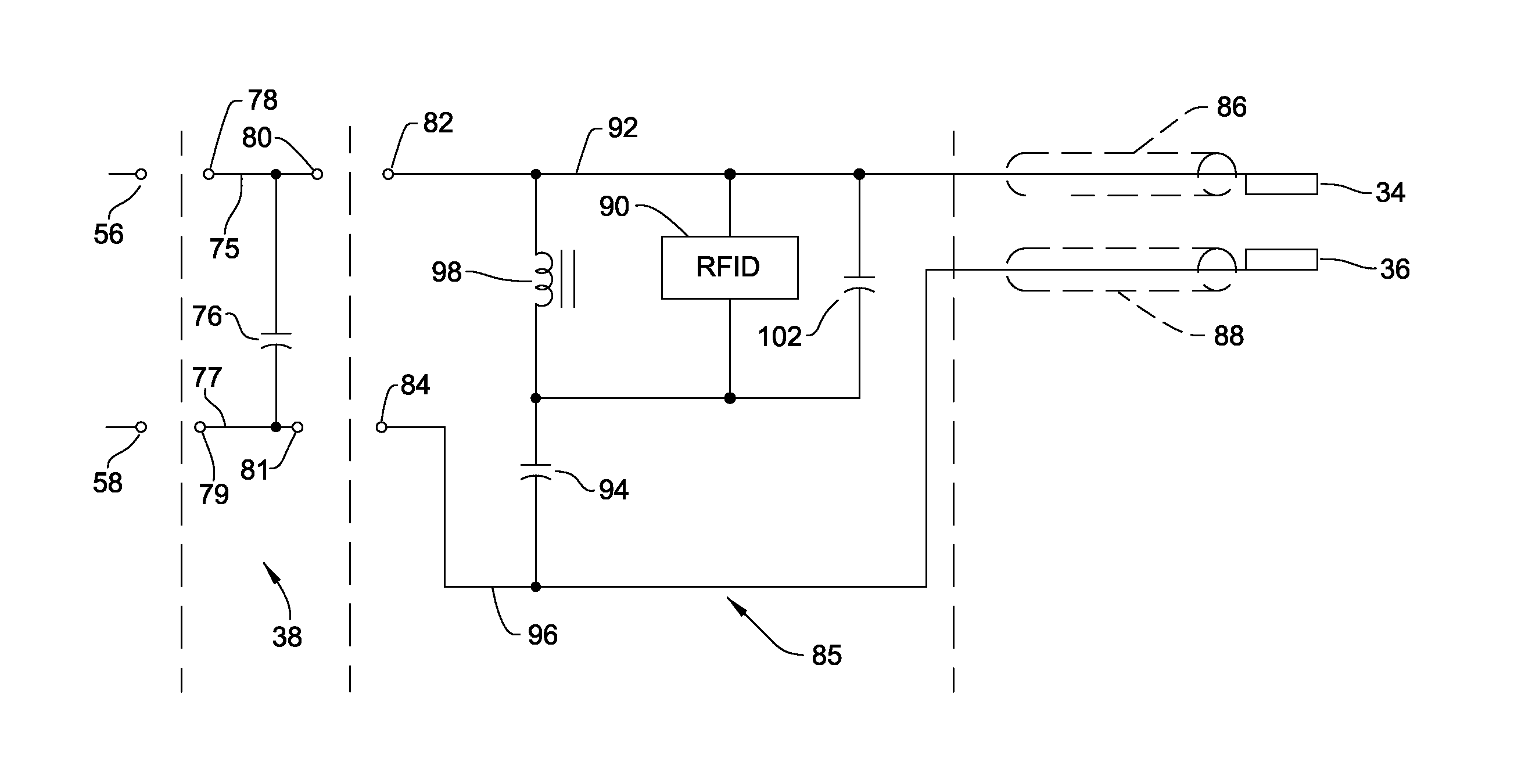
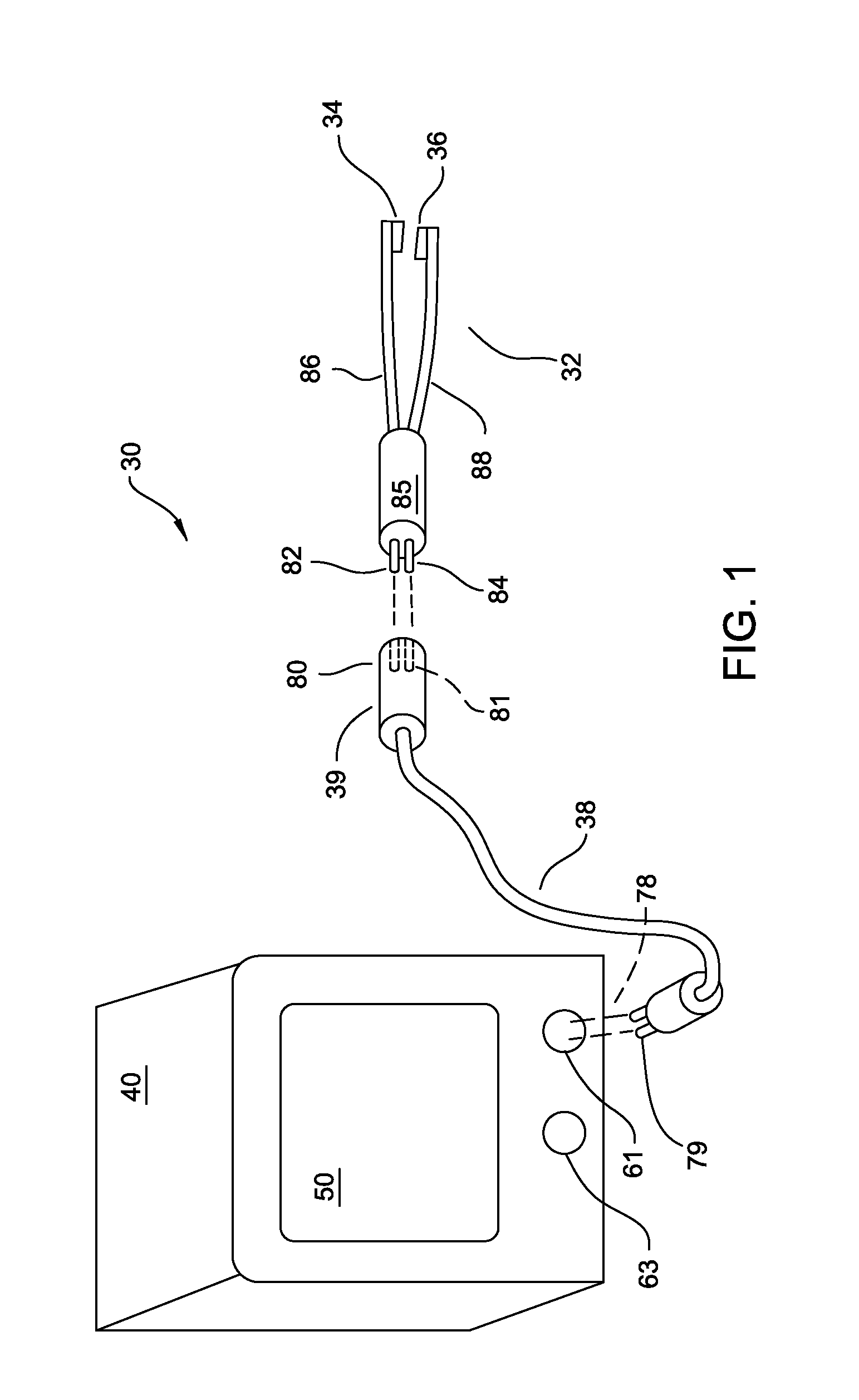
[0038]A surgical tool system 30, specifically an electrosurgical tool system, of this invention is initially described by reference to FIG. 1. System 30 includes an electrosurgical tool 32. Tool 32 of FIG. 1 is a pair of forceps. This type of tool is a bipolar tool in that the opposed surfaces at the ends of the tool tines 86 and 88 are formed to function as opposed electrodes 34 and 36, respectively. System 30 includes a console 40 that sources power to the tool 32. The power signal is sourced through a cable 38 that extends between the console 40 and the tool 32.

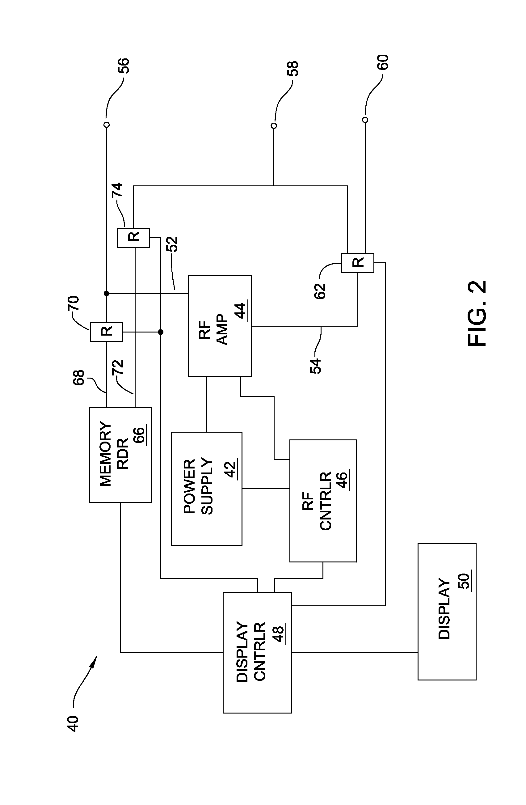
[0039]Console 40, as seen in FIG. 2, includes a power supply 42 and an RF amplifier 44. Power supply 42 outputs a constant DC voltage to the RF amplifier 44. RF amplifier 44 converts the signal from the power supply 42 into an AC power signal that is applied across the tool electrodes 34 and 36. In one version of the invention, RF amplifier 44 consists of an H-bridge and a series of inductors, capacitors ...


PUM


Abstract

A surgical tool system with a powered tool that includes a memory in which data describing the characteristics of the power signals that are to be sourced to the toll are stored. A control console based on the data in the tool memory sources the power signal to the tool. Both the data signals written out from the tool memory and the power signals from the console are exchanged over common console terminals and common tool terminals. An isolation circuit in the tool prevents the applied power signals from the console from adversely effecting the tool memory.

Description

RELATIONSHIP TO EARLIER FILED APPLICATION[0001]This application claims priority under 35 U.S.C. Sec. 119 to U.S. Prov. Pat. App. No. 61 / 050,430, filed 5 May 2008, the contents of which are explicitly incorporated herein by reference.FIELD OF THE INVENTION[0002]This invention is generally related to a surgical tool system that includes a surgical tool with a power generating unit and a console, the console able to read data in a memory integral with the tool over the conductors over which power is sourced to the tool.BACKGROUND OF THE INVENTION[0003]The ability to perform modern surgical procedures is facilitated in part by the development of instruments, sometimes referred to as tools, able to shape, remove or transform tissue. Electrosurgical tools are one such class of instruments. An electrosurgical tool system includes both a tool and a control console. The tool system includes at least two electrodes. The console sources a current between the electrodes. Some electrosurgical to...

Claims


Application Information

Patent Timeline
Patent Type & Authority Patents(United States)
IPC IPC(8): A61B18/14
CPCA61B5/01A61B5/145A61B2018/00178A61B2017/00084A61B18/14A61B2562/08A61B2018/00988A61B18/1233A61B2019/448A61B18/1442A61B2018/00958A61B90/98
Inventor MALACKOWSKI, DONALD W.HOEKSTRA, PAUL M.
Owner STRYKER CORP
Why Eureka
Try Eureka