
Electric road flare

Active Publication Date: 2014-07-22
DAUDELIN STEVEN
View PDF40 Cites 43 Cited by
  • Summary
  • Abstract
  • Description
  • Claims
  • Application Information

AI Technical Summary

Benefits of technology

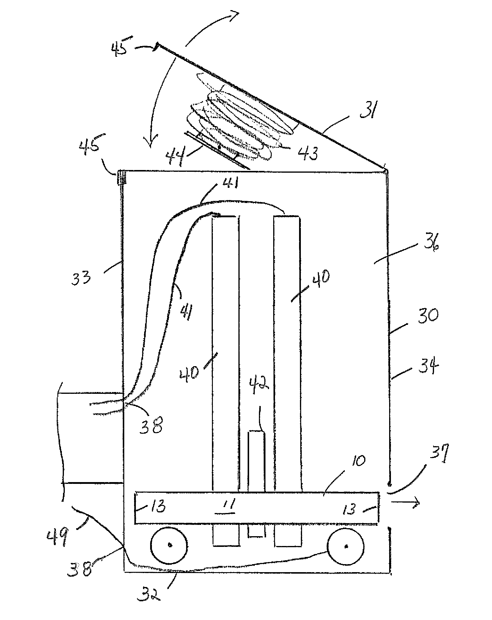
The present invention provides an emergency signaling device that is durable, safe, and easy to use. It includes a battery-operated LED light that is placed near reflective material to extend or direct the light pulsing. The device is also designed to be water resistant and quickly turned on and off. The invention also includes a deployment pack that can hold multiple devices and safely and efficiently deploy them in emergency situations. This allows people to quickly and safely mark the road without being exposed to dangerous conditions.

Problems solved by technology

However, conventional ignition type flares have several drawbacks.
Such flares are a fire hazard, not to mention a hazard to the individuals using them.
Once a flare has been ignited, it is not safe for an individual to move or relocate it.
The individual could burn their clothes, or their skin, or injure others.
Moreover, combustible flares could ignite spilt fuel or dry brush along a roadside.

Method used


Image

  • Electric road flare
  • Electric road flare
  • Electric road flare

Examples


Embodiment Construction

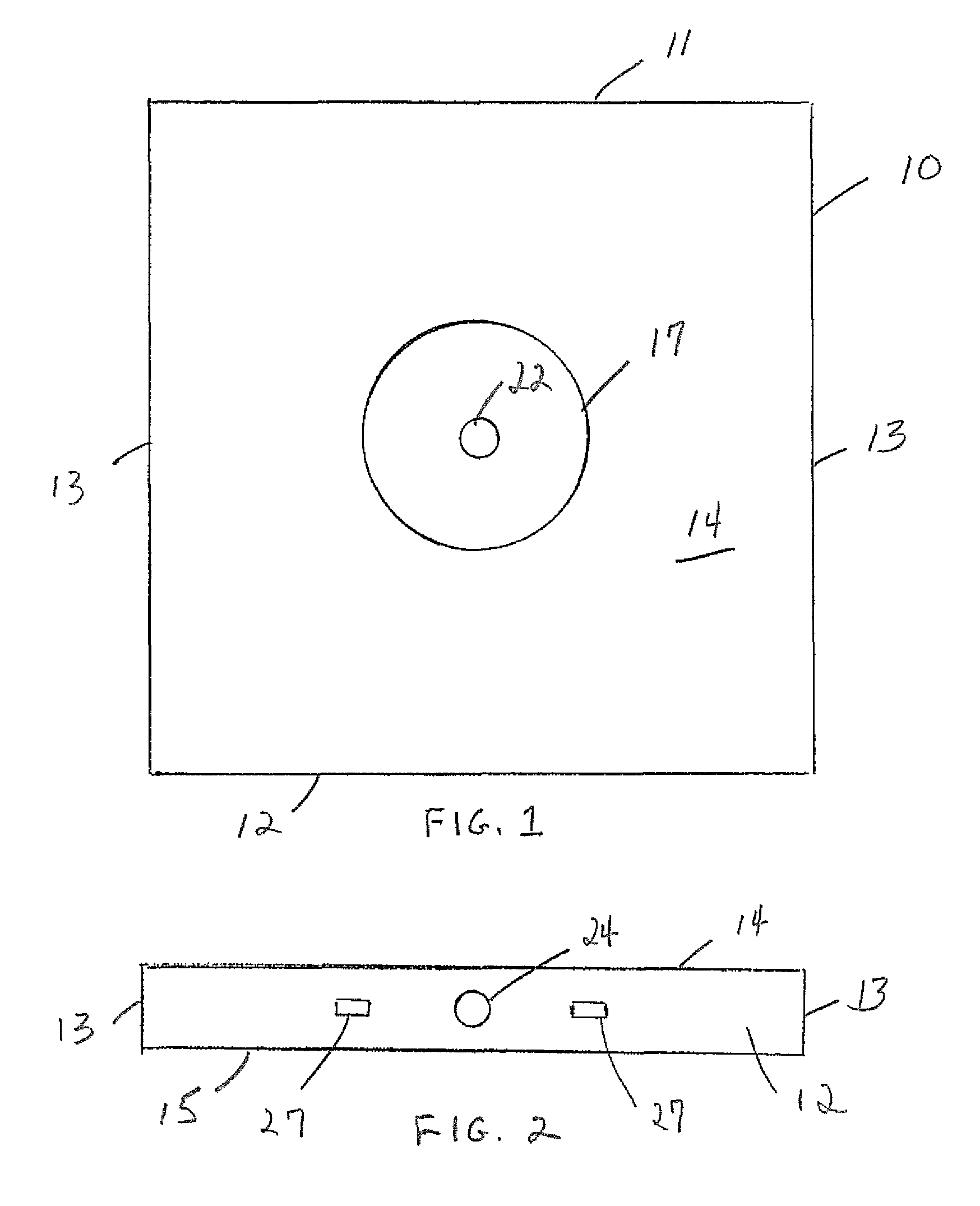
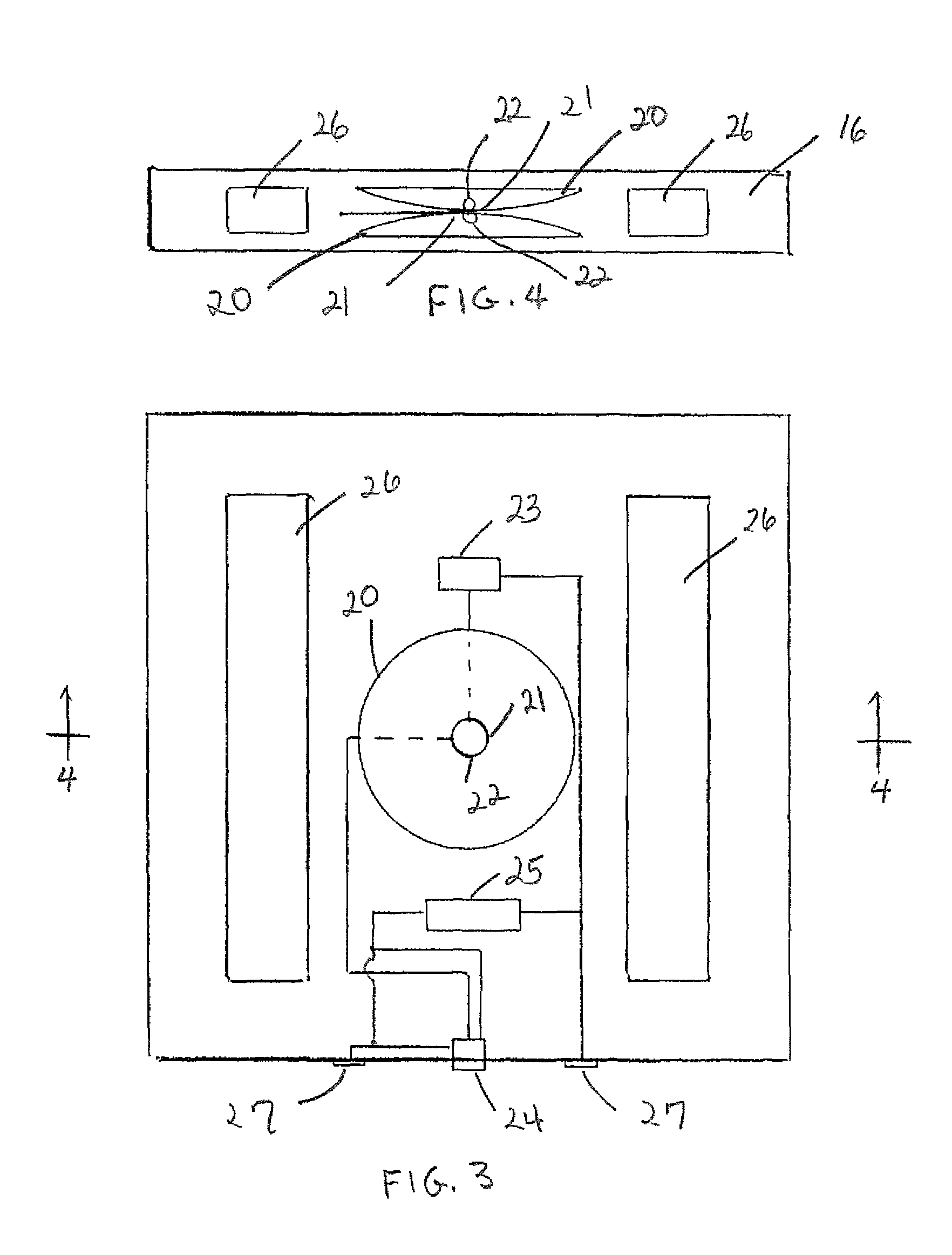
[0016]Referring to the drawings in detail wherein like elements are indicated by like numerals, there is shown an electric road flare 10 according to the principles of the present invention. The flare 10 is generally rectangular and has a top edge 11, bottom edge 12, two opposite side edges 13, an upper planar surface 14, and an opposite under planar surface 15, said edges and surfaces defining a flare interior 16. The upper and under surfaces 14, 15 each have an annular central transparent area 17. The flare 10 is generally flat having a uniform thickness between upper and under surfaces of approximately 0.5 inches.

[0017]The flare interior 16 contains two generally annular, concave reflectors 20, centrally located, each reflector 20 opening onto a said surface central transparent area 17. Each reflector 20 has a light emitting diode (LED) 22 positioned at the reflector vertex 21. The LEDs 22 are electrically connected to a flasher circuit 23 which pulses the LEDs at a predetermined...


PUM


Abstract

A deployment pack containing a number of electric road flares is provided. The pack is attached to an emergency vehicle. The pack is adapted to deploy a single flare at a time. Each flare includes two, battery-operated, light emitting diodes (LEDs), pulsed at a predetermined rate. Each LED is placed adjacent reflective material to extend or direct the light pulsing from the LED. The pack provides battery charging means to each electric road flare while contained in the pack interior. The pack also provides means for activating each flare before it is deployed from the pack. Each flare contains two metallic roads providing means for flare retrieval by a magnetic pick-up tool.

Description

CROSS-REFERENCE TO RELATED APPLICATIONS[0001]Applicant claims the priority benefits of U.S. provisional Patent Application No. 61 / 595,377, filed Feb. 6, 2012.BACKGROUND OF THE INVENTION[0002]This invention relates to lighting devices, and in particular, to safety lighting devices for providing a warning or alert to persons or vehicles within the vicinity of the lighting device.[0003]At an incident, such as a traffic accident, an individual usually distributes a plurality of road flares on the road as a temporary divider or warning on a roadway. The road flares alert other drivers that there is an accident or other incident in front so as to separate the accident / incident from the roadway. One of the most common road flares is the ignition type disposable flare wherein the flare is simply ignited and directly disposed on the roadway. However, conventional ignition type flares have several drawbacks. Such flares are a fire hazard, not to mention a hazard to the individuals using them....

Claims


Application Information

Patent Timeline
IPC IPC(8): F21V33/00G08B5/22G08B5/00F21L4/00B65D85/38G08B5/36
CPCG08B5/006B60Q7/005E01F9/012E01F9/014E01F9/016E01F9/065E01F9/688E01F9/70E01F9/615E01F9/559
Inventor DAUDELIN, STEVEN
Owner DAUDELIN STEVEN
Learn More