Image display device and transmission signal control method to be used in same

a transmission signal and display device technology, applied in the direction of instruments, computing, electric digital data processing, etc., can solve the problems of non-negligible amount of emi emission, and high emi emission level, so as to reduce emi emission

Active Publication Date: 2014-07-22
NEC LCD TECH CORP
View PDF5 Cites 0 Cited by
  • Summary
  • Abstract
  • Description
  • Claims
  • Application Information

AI Technical Summary

Benefits of technology

[0010]In view of the above, it is an object of the present invention to provide an image display device capable of reducing EMI emissions and a transmission signal control method to be applied to the image display device.

Problems solved by technology

However, the above methods for transmitting the data signal are one of reasons for heightening EMI (Electro-Magnetic Interference) emission levels in an image display device.
Even in the case of using the above method, in many cases, an image display device, a large-sized and high-definition type image display device in particular, is easily influenced by a gray level of a video signal to be inputted, arrangement of data signal transmission wirings, ground loop state of the image display device, thus resulting in suffering from high EMI emission levels, which further requires countermeasures.
For this reason, there is a fear that a non-negligible amount of the EMI emission occurs.
However, the above related arts have following problems.
Therefore, the direction of a current flowing through the entire liquid crystal device cannot be controlled, thus it is made impossible to sufficiently reduce EMI emissions.

Method used


Image

  • Image display device and transmission signal control method to be used in same
  • Image display device and transmission signal control method to be used in same
  • Image display device and transmission signal control method to be used in same

Examples


first embodiment

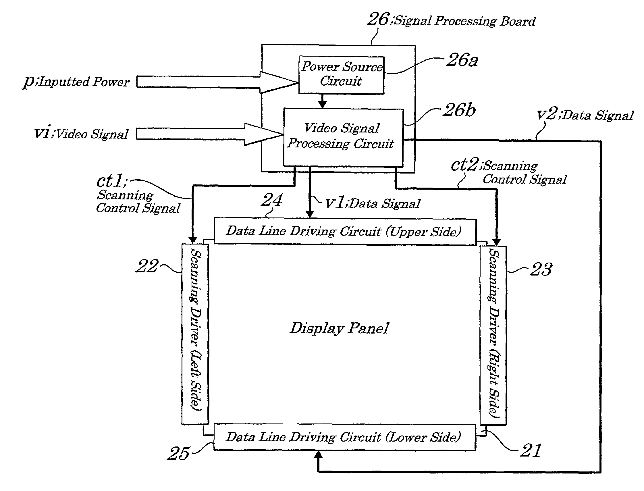
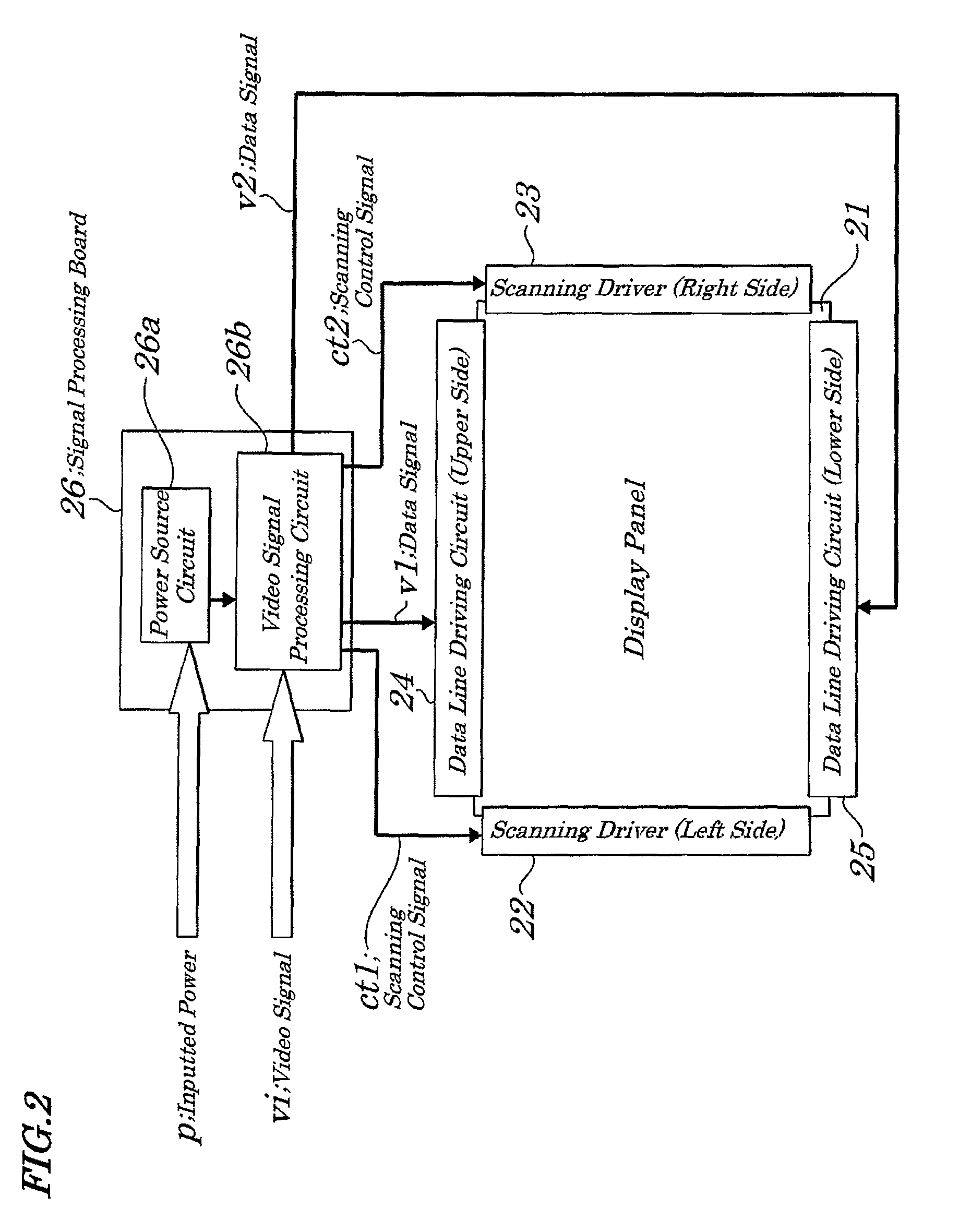
[0056]FIG. 2 is a block diagram showing main portions of an image display device of the first exemplary embodiment of the present invention. The image display device of the exemplary embodiment being a liquid crystal display device, includes, as shown in FIG. 2, a display panel 21, scanning drivers 22 and 23, data line driving circuits 24 and 25, and a signal processing board 26. The display panel 21 is made up of a liquid crystal panel having predetermined columns of data lines (not shown), predetermined rows of scanning lines (not shown), and each pixel disposed at the intersection between each of the data lines and each of the scanning lines.

[0057]The scanning driver 22, based on a scanning control signal ct1 fed from the signal processing board 26, outputs a scanning line driving signal to drive each scanning line on a left side in a predetermined order (for example, line-sequentially). The scanning driver 23, based on a scanning control signal ct2 fed from the signal processing...

second embodiment

[0075]FIG. 10 is another example of setting initial polarities of invert signals nA, nB, nC, and nD by an invert signal initial polarity setting section 46 in FIG. 3, according to a second exemplary embodiment of the present invention.

[0076]The invert signal initial polarity setting section 46, as shown in FIG. 10, performs the setting so that the initial polarity of the invert signal nA to be supplied to the source drivers 31 and 32 mounted on the left upper side of the display panel 21 is reversed to that of the invert signal nC to be supplied to the source drivers 51 and 52 mounted on the left lower side of the display panel 21 and so that the initial polarity of the invert signal nB to be supplied to the source drivers 37 and 38 mounted on the right upper side of the display panel 21 is reversed to that of the invert signal nD to be supplied to the source drivers 57 and 58 mounted on the right lower side of the display panel 21. That is, the initial polarities of the invert sign...


PUM


Abstract

An image display device and a transmission signal control method to be used in same and more particularly to the image display device and the transmission signal control method that can be suitably used when transmission wirings for data signal based on a video signal become complicated due to configurations of a large-sized and high-definition image display device.

Description

INCORPORATION BY REFERENCE[0001]This application is based upon and claims the benefit of priorities from Japanese Patent Application Nos. 2010-208635, filed on Sep. 16, 2010 and 2011-105735 filed on May 10, 2011, the disclosures of which are incorporated herein in its entirety by reference.BACKGROUND OF THE INVENTION[0002]1. Field of the Invention[0003]The present invention relates to an image display device and a transmission signal control method to be used in same and more particularly to the image display device and the transmission signal control method that can be suitably used when transmission wirings for data signal based on a video signal become complicated due to configurations of a large-sized and high-definition image display device.[0004]2. Description of the Related Art[0005]In an image display device such as a liquid crystal display device, there are mounted a driver IC to drive a display panel, a timing controller to output a control signal obtained by performing ti...

Claims


Application Information

Patent Timeline
Patent Type & Authority Patents(United States)
IPC IPC(8): G09G5/00
CPCG09G3/3688G09G3/3614G09G2330/06
Inventor OOGA, KOUICHI
Owner NEC LCD TECH CORP
Why Eureka
Try Eureka