Soft-switching for high-frequency power conversion

a technology of high-frequency power conversion and soft-switching, which is applied in the direction of efficient power electronics conversion, electric variable regulation, instruments, etc., can solve the problems of limiting the frequency at which the converter can be operated, limiting the ability to reduce the reactive components of the converter, and thus the size and weight of the converter, so as to reduce the rate of rise of the voltage level, improve the emi emission level, and reduce the effect of turn-off loss

Inactive Publication Date: 2018-11-08
EMD TECH
View PDF7 Cites 4 Cited by
  • Summary
  • Abstract
  • Description
  • Claims
  • Application Information

AI Technical Summary

Benefits of technology

[0029]Depending on the various embodiments, our switching is accomplished by connecting a split inductor, an auto-transformer or a isolation transformer, to a known and strategically chosen voltage level that is accessible in the circuit. It is important to note that beside achieving ZVS, the resonant nature of the transition entails that all voltages and currents feature controlled and weak rate of change throughout the turn-on transition. This significantly improves EMI emission levels. The beneficial action of the soft-switching cell is not restricted to the turn-on transition alone, but extends to the turn-off transition as well. In fact, the resonant capacitor (Cr), having been discharged to zero volts following the turn-on transition, is maintained in this discharged state throughout the conduction period and it is still discharged at the time of turn-off. As the main switching element turns off, the circuit current is automatically removed from the switching element and redirected into Cr through the coupling diode. This diversion of turn-off current from the main switching element greatly lessens the turn-off loss even in the presence of some residual current-tail. Furthermore, as was the case during turn-on, the presence of Cr greatly reduces the rate of rise of the voltage level across the switching element with consequent improvement of EMI emission.
[0030]We also offer a distinct advantage wherein the resonant transition is calibrated in such a way that no significant current is expected to circulate in the reverse direction, from emitter to collector of neither the main switching device nor the auxiliary switching device present in the soft-switching cell. This minimizes conduction loss and removes the need for large and expensive free-wheeling protection diodes across the switching devices.
[0031]Since the soft switching cell contains an actively controlled device (Qaux), the control mechanism / method for the existing power circuit is modified. The control mechanism / method in a basic form includes: (1) means for driving Qaux (2) means for detecting the end of the half-wavelength transition and (3) means of allowing full demagnetization of the transformer. Furthermore, the control logic may also include frequency foldback for low load operation and a back-up timer for preventing excessively protracted activation of Qaux.
[0032]The soft-switching cell provides significant reduction of both switching loss and EMI emissions. In the particular case of higher power applications, the soft-switching cell extends the effective frequency range of IGBTs from a maximum of 20 kHz to beyond 100 kHz.

Problems solved by technology

Conventional prior art pulse-width-modulated converters experience substantial switching losses when operated at high frequencies.
These switching losses limit the frequency at which the converter can be operated, which in turn limits the ability to reduce the size and weight of the converter reactive components and hence the size and weight of the converter.
There are several existing switching technologies, where switching losses were reduced only at the expense of greatly increased voltage / current stresses of the switches; this frequently leads to a substantial increase in conduction loss.
However, in single-ended ZVS-QRC topologies, the active switch suffers from an excessive voltage stress which is proportional to the load range.
The parasitic junction capacitance of the rectifier diode interacts with the large resonant inductor, resulting in severe switching oscillation noise.
Nevertheless, both active and passive switches in a ZVS-MRC are subjected to voltage and current stresses significantly higher than those in their PWM counterparts.
Although the switching losses are significantly reduced, the conduction loss increases significantly.
This resonant inductor also introduces additional core loss and copper loss.
However, the switches in a ZVS-QSC suffer from a high current stress which can be more than twice of that in its PWM counterpart; thus, the conduction losses are greatly increased.
In addition, the high turn-off current of the main switch tends to increase the turn-off loss, which is particularly relevant for minority-carrier power switch devices, such as IGBTs and BJTs.
At a high switching frequency, a fast-recovery rectifier produces a significant reverse-recovery-related loss when it is switched under a “hard-switching” condition.

Method used


Image

  • Soft-switching for high-frequency power conversion
  • Soft-switching for high-frequency power conversion
  • Soft-switching for high-frequency power conversion

Examples


Embodiment Construction

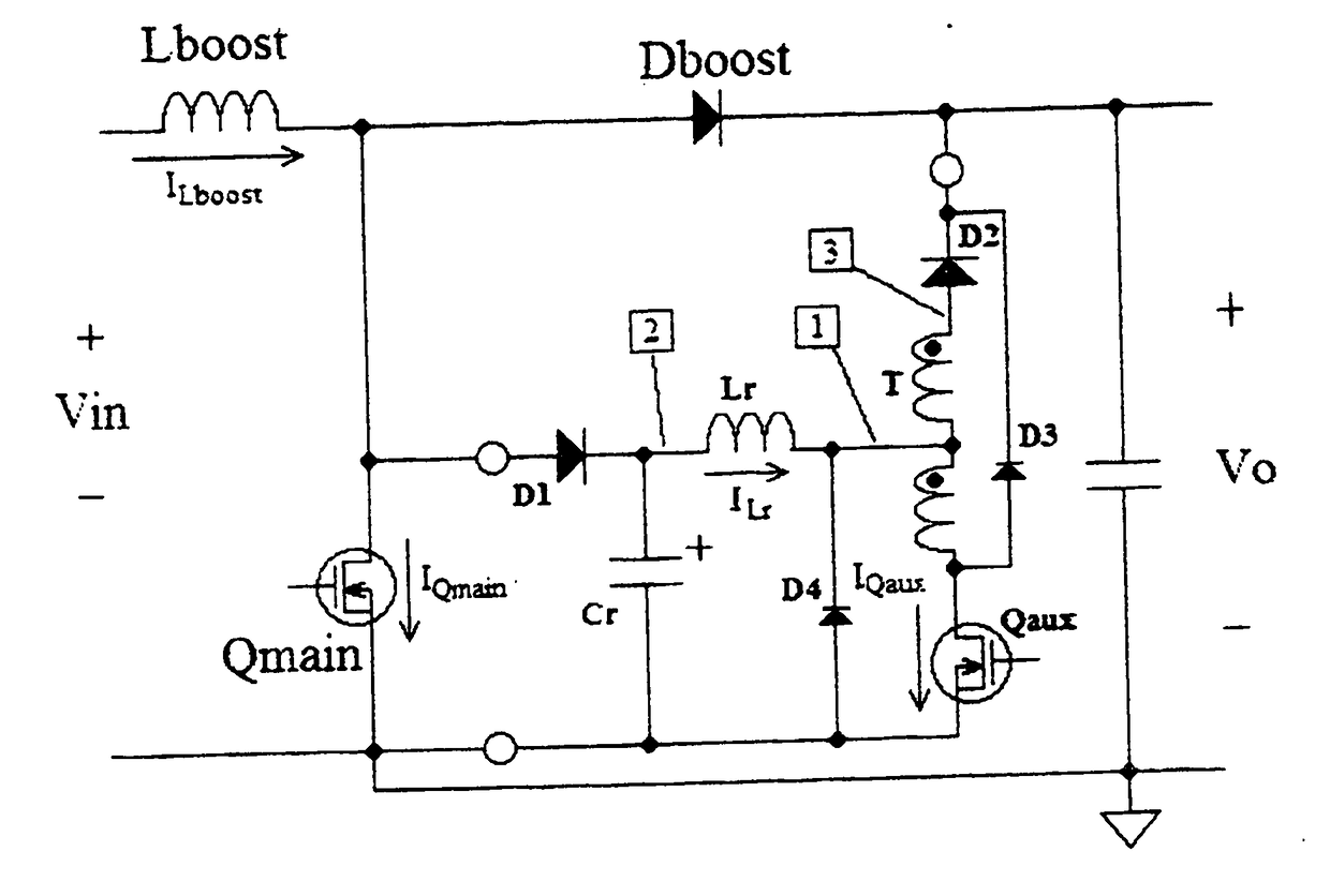
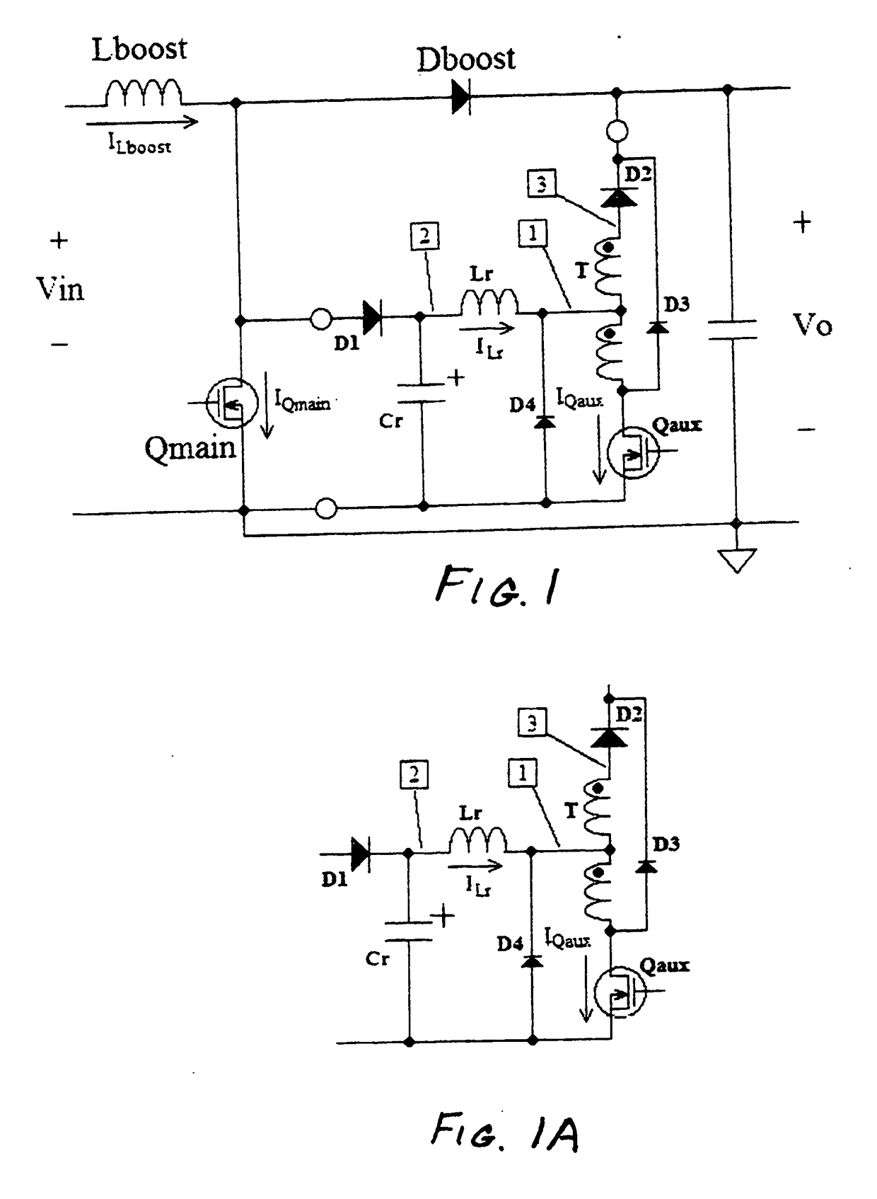
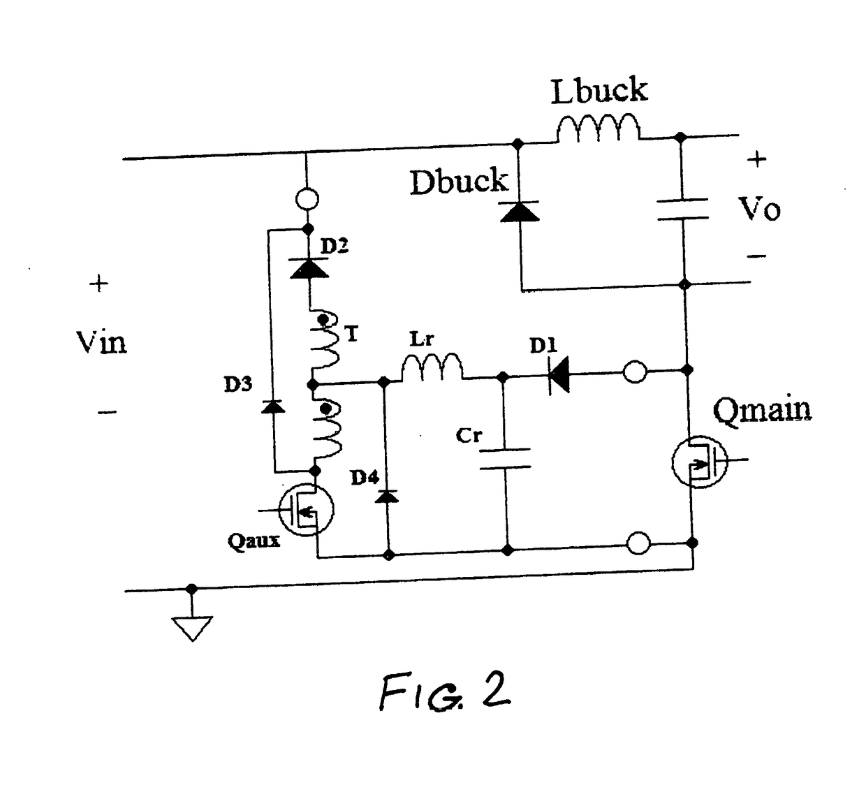
[0046]FIGS. 1, 2, 3, 4, and 5 illustrates schematically embodiments of different power conversion topologies modified with a soft-switching cell (SSC) shown in FIG. 1A. The soft-switching cell includes a split inductor, a resonant inductor, a resonant capacitor, two diodes, and a controlled semiconductor. The soft-switching cell alternatively includes a transformer having isolated windings, a resonant inductor, a resonant capacitor, two diodes and a controlled semiconductor. In order to illustrate its operation, FIG. 6 shows the relevant signal waveforms relative to the boost converter shown in FIG. 1. Referring to FIG. 6, starting at a time t0 when Qmain is not conducting, Dboost is conducting, Lr carries no current and Cr is charged at a voltage equal to Vo, the output voltage. At time t1, the control logic begins the turn-on transition by driving Qaux to its conductive state. Resonant inductor Lr begins to conduct current that impinges upon the center tap of the split inductor T;...


PUM


Abstract

A power converter designed for operation at high frequencies includes a soft-switching cell comprising a split inductor, a resonant inductor, a resonant capacitor, two diodes and a controlled semiconductor. Alternatively, the power converter includes a soft-switching cell comprising a transformer having isolated windings, a resonant inductor, a resonant capacitor, two diodes and a controlled semiconductor.

Description

[0001]This Application claims priority to U.S. application Ser. No. 62 / 602,289, filed Apr. 18, 2017, which is hereby incorporated by reference.FIELD OF THE INVENTION[0002]The present inventions are directed to soft-switching for power conversion.BACKGROUND OF THE INVENTION[0003]Conventional prior art pulse-width-modulated converters experience substantial switching losses when operated at high frequencies. These switching losses limit the frequency at which the converter can be operated, which in turn limits the ability to reduce the size and weight of the converter reactive components and hence the size and weight of the converter.[0004]There are several existing switching technologies, where switching losses were reduced only at the expense of greatly increased voltage / current stresses of the switches; this frequently leads to a substantial increase in conduction loss. For example, the active switch in a zero-voltage-switched (ZVS) quasi-resonant converter (QRC) is subjected to re...

Claims


Application Information

Patent Timeline
Patent Type & Authority Applications(United States)
IPC IPC(8): H02M3/158
CPCH02M3/1582H02M2001/0058H02M2001/0051H02M2003/1552H02M1/34H02M3/005Y02B70/10H02M1/342H02M1/0051H02M1/0058H02M3/1552
Inventor BELAND, ROBERTCARLI, GIAMPAOLO
Owner EMD TECH
Why Eureka
Try Eureka