Buck-boost power factory correction circuit

a technology of factory correction and power supply, which is applied in the direction of electric variable regulation, process and machine control, instruments, etc., can solve the problems of stressing the power transmission system, limiting the miniaturization of such power supplies, and large power drain from ac power lines or mains, so as to increase the energy stored in the first inductor

Inactive Publication Date: 2005-08-02
LOCKHEED MARTIN CORP
View PDF2 Cites 45 Cited by
  • Summary
  • Abstract
  • Description
  • Claims
  • Application Information

AI Technical Summary

Benefits of technology

[0007]A buck-boost power factor correcting supply according to an aspect of the invention is for generating a direct output voltage for energizing a load, and for operation from full-wave rectified line voltage which takes on voltage values both greater than and less than the direct output voltage. The supply comprises a first inductor including first and second terminals. A buck switch is connected to a terminal of the source of full-wave rectified line voltage and to the first terminal of the first inductor. An output capacitance including a first terminal is connected to a reference potential and also includes a second terminal at which the direct output voltage is generated for use by the load. A free-wheeling unidirectional current conducting means is provided. The free-wheeling unidirectional current conducting means includes a first terminal connected to the reference potential and a second terminal connected to the first terminal of the first inductor, for providing a path for the flow of current through the first inductor during at least some intervals during which the buck switch is nonconductive. A blocking unidirectional current conducting means includes a first terminal connected to the second terminal of the first inductor and a second terminal connected to the second terminal of the output capacitance, and is poled for blocking discharge of the output capacitance in a direction other than to the load. A boost switch is connected to the second terminal of the first inductor and to the reference potential, for, during at least some intervals in which the buck switch is conductive, connecting the second terminal of the first inductor to the reference potential, for thereby increasing the energy stored in the first inductor. A first soft-switching circuit includes the serial combination of a first soft-switching switch and a saturable second inductor. The first soft-switching circuit is coupled in parallel with the boost switch. A second soft-switching circuit includes the serial combination of a second soft-switching switch and a saturable third inductor. The second soft-switching circuit is connected in parallel with the buck switch. A control means is connected to the buck switch, the boost switch, and to the first and second soft-switching switches, for, (a) when the full-wave rectified line voltage is less than the direct output voltage, maintaining the buck switch conductive, and from time to time rendering the boost switch alternately conductive and nonconductive, and, prior to the transitions of the boost switch from the nonconductive to the conductive state, rendering the first soft switching switch conductive, whereby the first soft switching circuit reduces the voltage appearing across the boost switch at the time the boost switch is rendered conductive by comparison with the voltage appearing across the boost switch in the absence of the first soft switching circuit, and (b) when the full-wave rectified line voltage is greater than the direct output voltage, maintaining the boost switch and the first soft switching switch nonconductive, and from time to time rendering the buck switch alternately conductive and nonconductive, and, prior to transitions of the buck switch from the nonconductive to the conductive state, rendering the second soft switching switch conductive, whereby the second soft switching circuit reduces the voltage appearing across the buck switch at the time the buck switch is rendered conductive by comparison with the voltage appearing across the buck switch in the absence of the second soft switching circuit.

Problems solved by technology

A limiting factor in the miniaturization of such power supplies is the heat generated during the switching of the power switches of the supply.
When large amounts of power are to be supplied to an equipment, the power drain from the AC power lines or mains can be large.
These larger currents, in turn, undesirably tend to stress the power transmission system.

Method used


Image

  • Buck-boost power factory correction circuit
  • Buck-boost power factory correction circuit
  • Buck-boost power factory correction circuit

Examples


Embodiment Construction

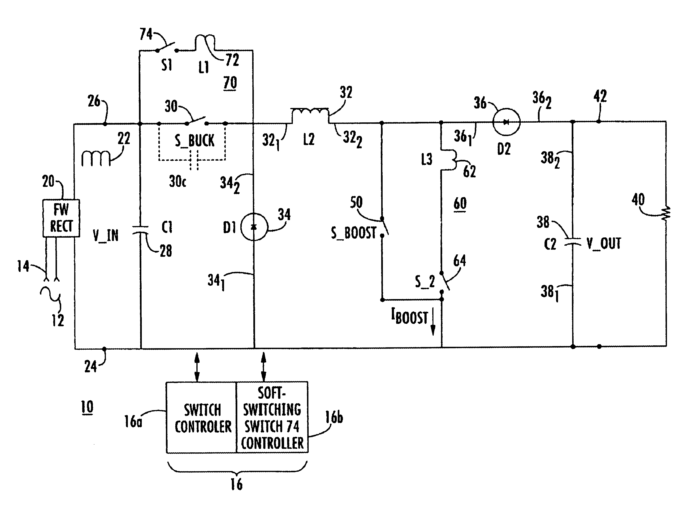
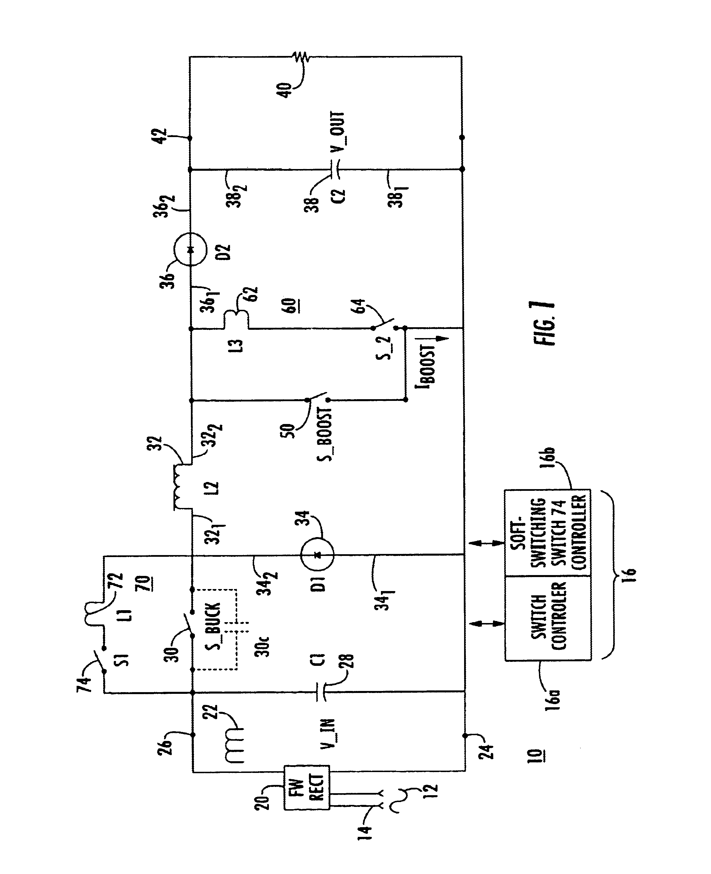
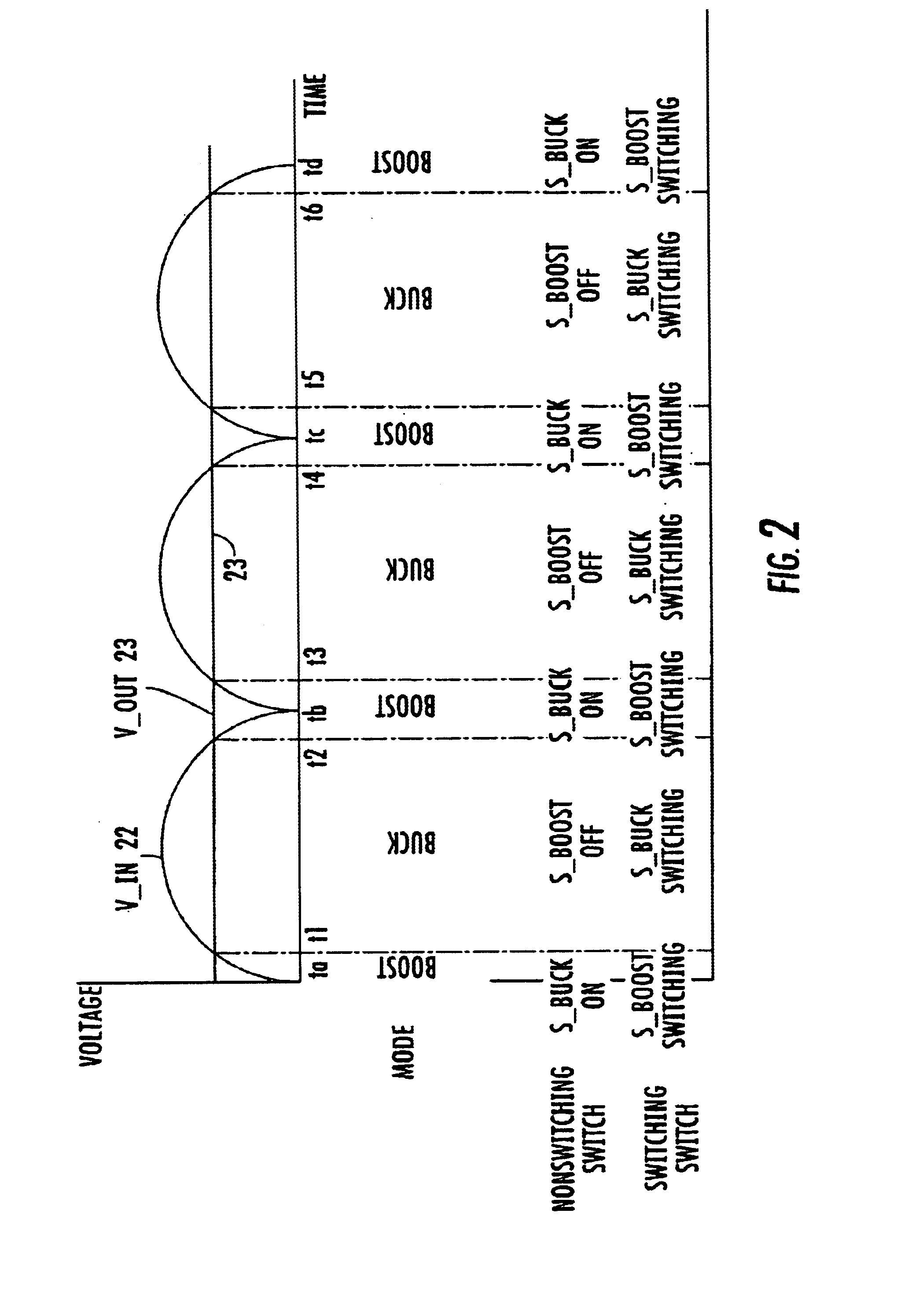
[0016]FIG. 1 is a simplified diagram in block and schematic form of a switching buck-boost power supply designated generally as 10, for operation from alternating power line mains voltage. In FIG. 1, the alternating power line mains voltage 12 is applied by way of terminals 14 to a full wave rectifier (FW Rect) 20. Rectifier 20 rectifies or “makes straight” the applied alternating mains voltage, to thereby produce the pulsating direct voltage (V_in) illustrated as 22 in FIG. 2. The pulsating direct voltage is produced “between” terminals 24 and 26, where terminal 24 is taken to be a reference terminal, which may be “ground.” Those skilled in the art know that the term “between” in electrical parlance is distinct from ordinary usage in a mechanical context, and relates to the ending points of the electric field lines associated with the voltage, and not to any physical position. The pulsating direct voltage 22 is slightly filtered by a capacitor (C1) 28, without changing the essence ...


PUM


Abstract

A buck-boost switching converter includes a soft-switching circuit coupled across the boost switch, controlled to establish a short-circuit across the boost switch prior to turn-on of the boost switch. The converter also includes a second soft-switching circuit including a third switch and a saturable inductor coupled across the buck switch. The third switch is rendered conductive sufficiently before the buck switch so that a half-cycle of resonance can occur between the saturable inductor and the buck switch.

Description

FIELD OF THE INVENTION[0001]This invention relates to switching power supplies, and more particularly to buck-boost power supplies in which at least the buck switch soft switches.BACKGROUND OF THE INVENTION[0002]Modern switching power supplies are used for powering a wide variety of solid-state equipment, such as computers, televisions, and communication equipments. The ability to perform power switching at high frequencies allows the use of miniaturized inductors, which in turn tends to reduce the weight and volume of the power supply. A limiting factor in the miniaturization of such power supplies is the heat generated during the switching of the power switches of the supply.[0003]When large amounts of power are to be supplied to an equipment, the power drain from the AC power lines or mains can be large. It is very desirable to reduce the load on the AC power lines by minimizing the current required to deliver a given amount of power. It is well known that the current in the AC p...

Claims


Application Information

Patent Timeline
Patent Type & Authority Patents(United States)
IPC IPC(8): G05F1/613G05F1/10H02M1/34H02M1/42H02M3/158
CPCH02M1/34H02M1/4208H02M3/1582H02M2001/342Y02B70/126Y02B70/1491H02M1/342Y02B70/10
Inventor PACALA, VIOREL MARK
Owner LOCKHEED MARTIN CORP
Why Eureka
Try Eureka