Drive unit and injection device

a technology of injection device and drive unit, which is applied in the direction of infusion needles, intravenous devices, other medical devices, etc., can solve the problems of glass breakage risk, achieve cost-effective production, improve energy storage, and dispense highly viscous drugs

Active Publication Date: 2018-04-26
YPSOMED AG
View PDF0 Cites 19 Cited by
  • Summary
  • Abstract
  • Description
  • Claims
  • Application Information

AI Technical Summary

Benefits of technology

[0007]Therefore, an aim of the invention is to indicate an improved energy storage for an administration device which enables the dispensing of highly viscous drugs and in the process can be produced cost effectively while also allowing a cost-effective production of the administration device.
[0027]In an advantageous combination, the spring assembly can comprise a pretensioned spring, wherein the spring tension can be held by the above-described anti-rotation device. In an advantageous addition, the spring assembly comprises a cover element and a bottom element. In another aspect, the bottom element is arranged as a flange firmly on the spring shaft, and the cover element is formed as a separate element, which can be fixed at variable separation from the bottom element on the spring shaft and / or on the spring sleeve, so that the spring can be protected from external mechanical influences. Subsequently, the spring assembly can be transported with a pretensioned spring. The spring can be supported and / or guided by the bottom element and / or cover element. In an alternative design, the spring assembly can also contain two, three or more pretensioned springs, preferably with a cover element for each spring.
[0033]In this embodiment, in a first assembly step, the spring assembly is shifted onto the proximal end of the preassembled drive unit. Here, the described threaded rod is brought into a rotationally fixed connection with the spring shaft, so that a rotational movement of the shaft is transmitted to the threaded rod. In the spring assembly, in this state, blocking means of the spring sleeve and the element complementary thereto are engaged, so that the spring of the spring assembly can be pretensioned. Furthermore, on the mechanism holder, a release element is arranged which, during the shifting of the spring assembly relative to the blocking means reaches a releasing position. From this releasing position, an additional relative movement between release element and blocking means is possible, by means of which the engagement between blocking means and the complementary element is released. In this so-called trigger position, a relative turning between spring shaft and spring sleeve is possible, which means that, in this state, torque can be guided from the spring toward the outside of the spring assembly.
[0035]In an advantageous design of the connection between mechanism holder and housing part, the connection is established by a bayonet closure. This type of connection has the advantage that, in the establishment of the firm connection, the release element of the mechanism holder can also be moved from the releasing position into the released position. For this purpose, on the periphery of the mechanism holder, bayonet lugs can be arranged, which can engage with bayonet slots on an inner surface of the housing part. The bayonet slots here have at least one part extending axially and at least another portion extending in the circumferential direction. In the second assembly step, the bayonet slots engage with the axially extending part of the bayonet slots, so that the housing part can be shifted over the mechanism holder. At the end of this movement, the spring sleeve is connected in a rotationally fixed manner to the housing.

Problems solved by technology

Then, in order to be able to achieve a regular administration of a drug, pressure springs have to be pretensioned sufficiently, which, in the case of the use of finished syringes made of glass as a drug container, increases the risk of glass breakage due to triggering of the administration device.

Method used


Image

  • Drive unit and injection device
  • Drive unit and injection device
  • Drive unit and injection device

Examples


Embodiment Construction

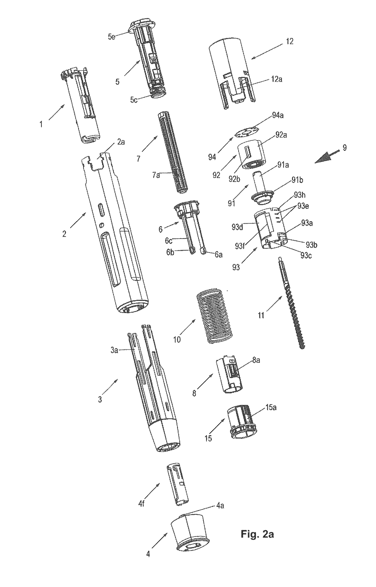
[0053]FIGS. 1-10d show a spring assembly according to the invention with a corresponding injection device, an autoinjector, as well as the different assembly steps of the associated method according to the invention.

[0054]FIGS. 11-12d thereafter show the use of spring assemblies according to the invention in an alternative administration device, namely a so-called autopen, an injection pen by means of which a manually settable dose can be administered using stored energy.

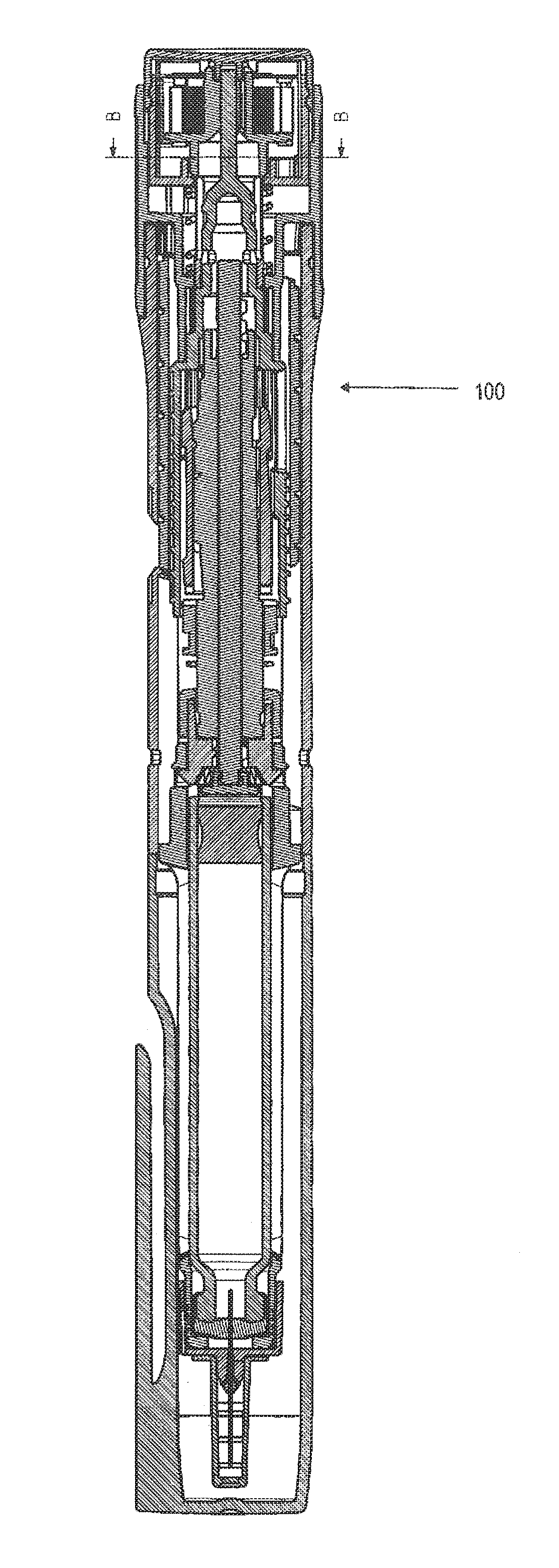
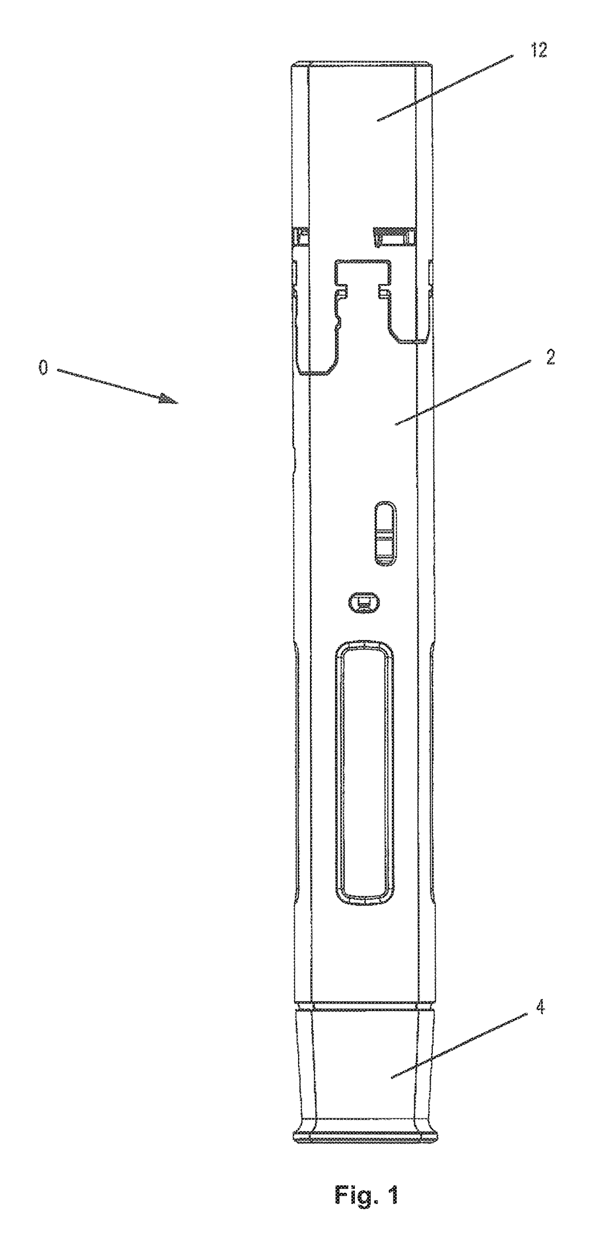
[0055]In reference to FIGS. 1-10d, below a first series of possible designs of the invention is described, based on an autoinjector 0 as represented in FIG. 1. Here, Swiss Patent Application 00904 / 15, which is a priority document to the instant application, is referenced and integrated in its entirety in the present application, since it also comprehensively describes the autoinjector 0 except for the spring assembly.

[0056]Next, the structure and function of the autoinjector 0 will be described in reference to FIGS....


PUM


Abstract

A spring assembly for an administering device includes a driving spring configured as a spiral spring and a spring shaft. An inner end of the spring is rotationally fixedly attached to the spring shaft. A spring sleeve extends around the circumferential region of the spring, wherein the outer end of the spring is connected to the spring sleeve in a rotationally fixed manner and a disk-type spring-sleeve cover is attached to the spring sleeve or the spring shaft. The flange and the spring-sleeve cover extend radially away from an axis of the spring shaft and the flange is arranged near a distal end of the spring shaft. A radial stop is arranged on the flange periphery, and a blocking element is arranged on the spring sleeve to be complementary to the radial stop for releasably rotationally securing to each other when the blocking element and the radial stop engage.

Description

CROSS-REFERENCE TO RELATED APPLICATIONS[0001]This application is a continuation of International Application No. PCT / CH2016 / 000093 filed Jun. 16, 2016, which claims priority to Swiss Application No. 00531 / 16 filed Apr. 21, 2016 and Swiss Application No. 00904 / 15 filed Jun. 23, 2015.BACKGROUND[0002]The invention relates to a spring assembly for an injection device, to a corresponding injection device and to a method for assembling these injection devices. In particular, the invention relates to an improved drive unit for an injection device and to a method for assembling this drive unit in the injection device.[0003]Here, the term “drug” comprises any flowable medical formulation which is suitable for controlled administration through a means such as, for example, a cannula or hollow needle, comprising, for example, a liquid, a solution, a gel or a fine suspension containing one or more medical active substances. Drug can refer to a composition with a single active substance or to a ...

Claims


Application Information

Patent Timeline
Patent Type & Authority Applications(United States)
IPC IPC(8): A61M5/20A61M5/145A61M5/315
CPCA61M5/2033A61M5/1454A61M5/31586A61M5/31585A61M2207/00A61M5/3204A61M2005/2013A61M2005/202A61M2005/2086A61M5/20A61M5/31583A61M5/3159A61M5/326A61M5/46A61M5/484A61M2005/3143A61M2005/3152A61M2005/3247A61M2005/3267A61M2205/3341A61M2205/581A61M2205/582A61M5/3157A61M5/31581
Inventor SCHRUL, CHRISTIANTSCHIRREN, MARKUSSCHENKER, SUSANNEHOSTETTLER, PATRICKSTREIT, URSINA
Owner YPSOMED AG
Why Eureka
Try Eureka