Electromechanical inductors and transformers

a technology of inductors and transformers, applied in the direction of electric variable regulation, process and machine control, instruments, etc., can solve the problems of limiting the size and performance limiting both mission duration and useful payload, and the bulkiest and most inefficient components of a power system. , to achieve the effect of high q, high energy density and high density inductive energy storag

Inactive Publication Date: 2012-01-26
UNIV OF FLORIDA RES FOUNDATION INC
View PDF0 Cites 20 Cited by
  • Summary
  • Abstract
  • Description
  • Claims
  • Application Information

AI Technical Summary

Benefits of technology

[0011]An embodiment of the present invention provides devices and systems for power electronic circuits. Embodiments of the present invention enable high density inductive energy storage by using electromechanical coupling between an electrically conducting inductive element and a mechanical resonator to passively store energy via both electromagnetic and mechanical mechanisms. As opposed to traditional magnetic core inductors, ultra high energy density and high Q are achieved in devices according to embodiments of the present invention via kinetic energy storage, thus avoiding the magnetic loss mechanisms and efficiency penalties associated with magnetic cores. In accordance with one embodiment of the present invention, the beneficial energy storage occurs over a limited frequency range, near the coupled system resonance. For switch-mode power converters, this is acceptable because switch-mode power converter circuits tend to operate at a constant switching frequency.
[0012]In one embodiment, a resonating inductor element is provided. The subject inductor can be achieved through electromechanical energy storage elements. In a further embodiment, the subject inductor can enhance the performance and reduce the size / mass of switch-mode dc:dc power supplies for small-scale (<100 W) power systems. In yet a further embodiment, the subject inductor can be designed to exhibit extreme inductance density (>100 μH / mm2) and low loss in the 50 kHz-50 MHz range. Applications of the subject inductors include ultra-miniaturized, single-chip power converters with order-of-magnitude size / mass reduction compared to the existing state-of-the art.

Problems solved by technology

Magnetic inductors and transformers are often the bulkiest, costliest, and most inefficient components in a power system.
These components can limit the size and performance of a power system, and thus a larger system as a whole.
For example, the power supply of an unmanned aerial vehicle (UAV) limits both mission duration and useful payload.
The size and efficiency of switch-mode dc:dc converters are currently limited by the required passive components (inductors / capacitors).
While the physics of semiconductor devices have enabled extreme size-reduction of solid-state devices (i.e. Moore's Law), electrical passive elements have not benefited from the same favorable scaling.
However, higher switching frequencies lead to higher power losses in both the electronics and the passive elements, and thus lower overall efficiencies.
At these frequencies, transistor switching losses begin to limit the overall efficiency.
Additionally, frequency-dependent power losses in magnetic materials present roadblocks for realizing high-Q inductors, which again limits efficiency.
Thus, existing size and performance limitations of electrical passive elements inhibit the realization of single-chip power converter solutions.
For inductors, however, there continues to be difficulties in achieving both the high inductances and high quality factors used to maintain overall converter efficiency.
While suitable magnetic films have exhibited relative permeabilities of 200-1000 in the MHz range, actual microfabricated inductors have not attained such a performance gain.
This shortfall has been attributed to geometric demagnetization effects, surface defects that inhibit domain wall motion, and the difficulties in achieving fully-closed magnetic cores.
For inductors, the quality factor (the ratio of energy stored to energy lost per cycle, where Q=ωL / R) presents another major design challenge.
In microscale inductors, thick electroplated coil windings are used to mitigate conduction losses, but the use of magnetic materials introduces additional power loss mechanisms, including hysteresis, eddy current, and excess loss in the magnetic cores.
The use of magnetic cores becomes more challenging as the switching frequency is increased because the magnetic eddy current losses scale quadratically with frequency.

Method used


Image

  • Electromechanical inductors and transformers
  • Electromechanical inductors and transformers
  • Electromechanical inductors and transformers

Examples


embodiment 1

[0067]2. The resonating inductor of embodiment 1, wherein the magnetic material is one or more permanent magnets.

[0068]3. The resonating inductor of embodiment wherein the magnetic material is one or more soft magnets.

[0069]4. The resonating inductor of embodiment 1, wherein the conductor is in the shape of a coil.

[0070]5. The resonating inductor of embodiment 1, wherein the conductor is in the shape of a straight or curved wire.

[0071]6. The resonating inductor of embodiment 1, further comprising flexures attached to the conductor and magnetic material to enable translational or rotational motion between the magnetic material and the conductor.

[0072]7. The resonating inductor of embodiment 1, wherein the resonating inductor is fabricated as a microelectromechanical inductor.

embodiment 7

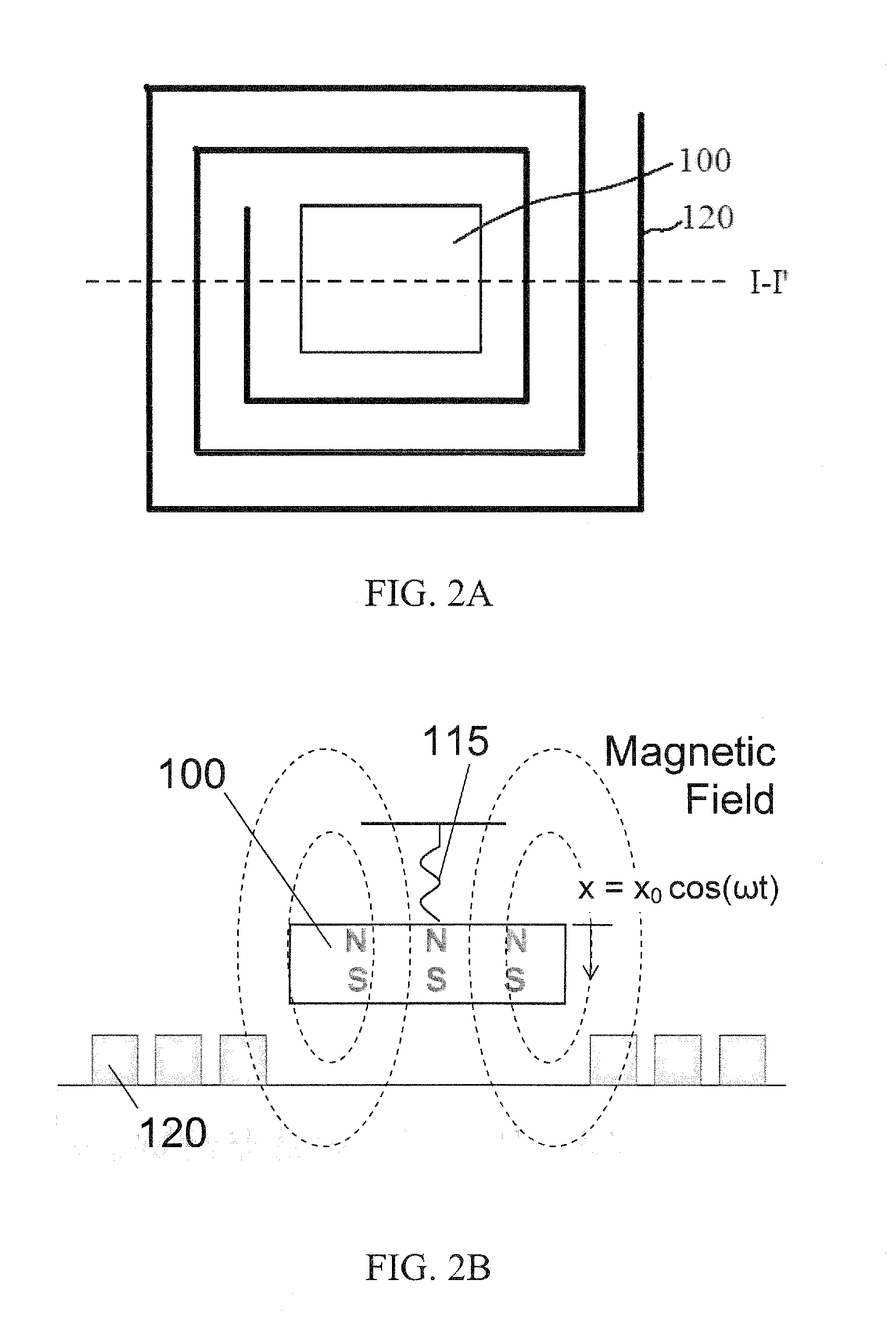
[0073]8. The MEMI of embodiment 7, wherein the conductor is a spiral coil and wherein the magnetic material is centrally disposed in the spiral coil.

[0074]9. The MEMI of embodiment 7, wherein the magnetic material is disposed on a compliant layer on a substrate, and configured to allow movement of the magnet.

[0075]10. The MEMI of embodiment 7, wherein the magnetic material is fixed on the substrate and the conductor is configured to allow movement of the conductor. The MEMI can further include additional magnets fixed on the substrate to affect flux in the coil.

[0076]11. The MEMI of embodiment 7, further comprising flexures or a cantilever attached to the conductor or magnetic material to enable translational or rotational motion between the magnetic material and the conductor.

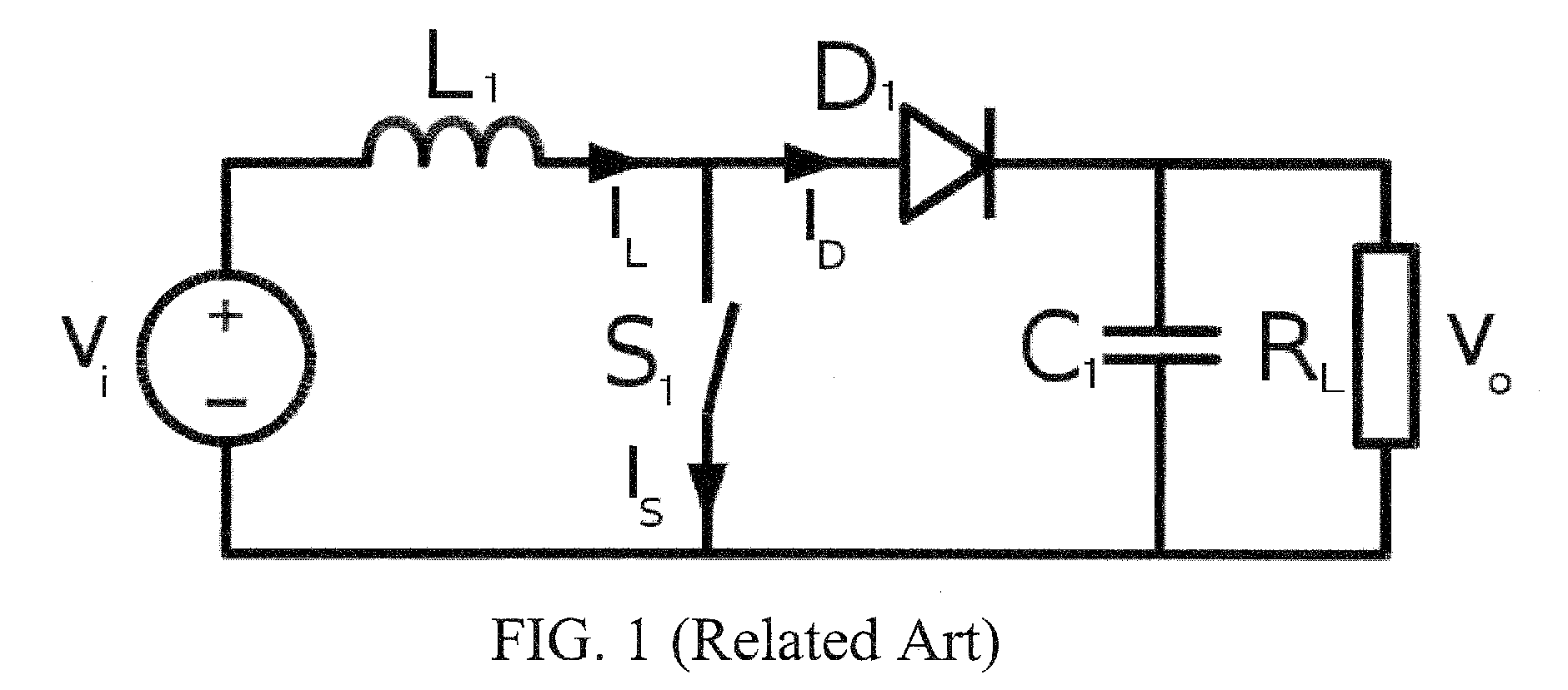
[0077]12. A switch-mode power converter, comprising:

[0078]a resonating inductor in series between an input voltage signal and a switch.

[0079]13. A resonating transformer, comprising:

[0080]the resonating induct...


PUM


Abstract

Devices and systems for power electronic circuits are provided. Embodiments of the present invention enable high density inductive energy storage by using electromechanical coupling between an electrically conducting inductive element and a mechanical resonator to passively store energy via both electromagnetic and mechanical mechanisms. A microelectromechanical inductor (MEMI) is provided utilizing a magnet and a conductor. In a specific embodiment, the MEMI includes a permanent magnet on a compliant layer centrally disposed within a spiral coil. In a further embodiment, a second coil is provided near the magnet to provide a resonating transducer.

Description

CROSS-REFERENCE TO RELATED APPLICATION[0001]This application claims the benefit of U.S. Provisional Application Ser. No. 61 / 865,589, filed Jun. 12, 2009, which is hereby incorporated by reference in its entirety, including all figures, tables and drawings.BACKGROUND OF INVENTION[0002]Magnetic inductors and transformers are often the bulkiest, costliest, and most inefficient components in a power system. These components can limit the size and performance of a power system, and thus a larger system as a whole. In mobile, wireless, or autonomous devices, size and efficiency play an even more prominent role. For example, the power supply of an unmanned aerial vehicle (UAV) limits both mission duration and useful payload. Additionally, many consumer electronic devices demand small, efficient power supplies to enhance mobility and useful lifespan between battery recharging / replacement. Since most existing portable systems rely on dc primary power sources (such as batteries, fuel cells, a...

Claims


Application Information

Patent Timeline
Patent Type & Authority Applications(United States)
IPC IPC(8): H02M3/22H02K33/00
CPCH01F29/10H02M3/22H02M3/155H01F5/00
Inventor ARNOLD, DAVID PATRICKCHENG, SHUOMEYER, CHRISTOPHER DAVID
Owner UNIV OF FLORIDA RES FOUNDATION INC
Why Eureka
Try Eureka