Soft switching high efficiency flyback converter

a converter and high-efficiency technology, applied in the field of soft switching high-efficiency flyback converters, can solve the problems of no regulation, communication across the isolation boundary, add complexity and parts, etc., and achieve the effects of reducing the size of the converter, preventing switching losses, and good us

Inactive Publication Date: 2005-12-08
DET INT HLDG LTD
View PDF15 Cites 45 Cited by
  • Summary
  • Abstract
  • Description
  • Claims
  • Application Information

AI Technical Summary

Benefits of technology

[0009] In accordance with this invention, a method and circuit are employed in which energy is pushed back to the input or primary circuit from the secondary in a power conversion circuit to vary the circuit's duty cycle and in this way regulate the circuit's output voltage. In a sense, the secondary changes the effective duty cycle by making the OFF time longer. This regulates the output. In the primary circuit, the extra energy that is pushed back is put to good use by providing zero voltage switching. This also prevents cross-conduction between the primary switch and the secondary's synchronous rectifier. Since zero volt switching can prevent switching losses at higher frequencies, higher frequencies can be employed to further reduce the size of the converter.
[0010] Controlling the timing of the secondary and primary MOSFETs serving as the synchronous rectifier and the primary switch is an important feature of this invention. The invention provides a simple method of achieving this and a general methodology.

Problems solved by technology

Among the greatest challenges is communication across the isolation boundary.
A first, main drawback of this approach is that there is no regulation.
The control is simple, but adding regulation would ordinarily add complexity and parts.
A second drawback is that for low output voltages the diode has a relatively large forward voltage drop.
A third drawback is the primary switch 8 does not have zero voltage switching in all situations.
However, this could introduce other problems including cross-conduction between the primary switch 8 and the synchronous rectifier which needs to be avoided.

Method used


Image

  • Soft switching high efficiency flyback converter
  • Soft switching high efficiency flyback converter
  • Soft switching high efficiency flyback converter

Examples


Embodiment Construction

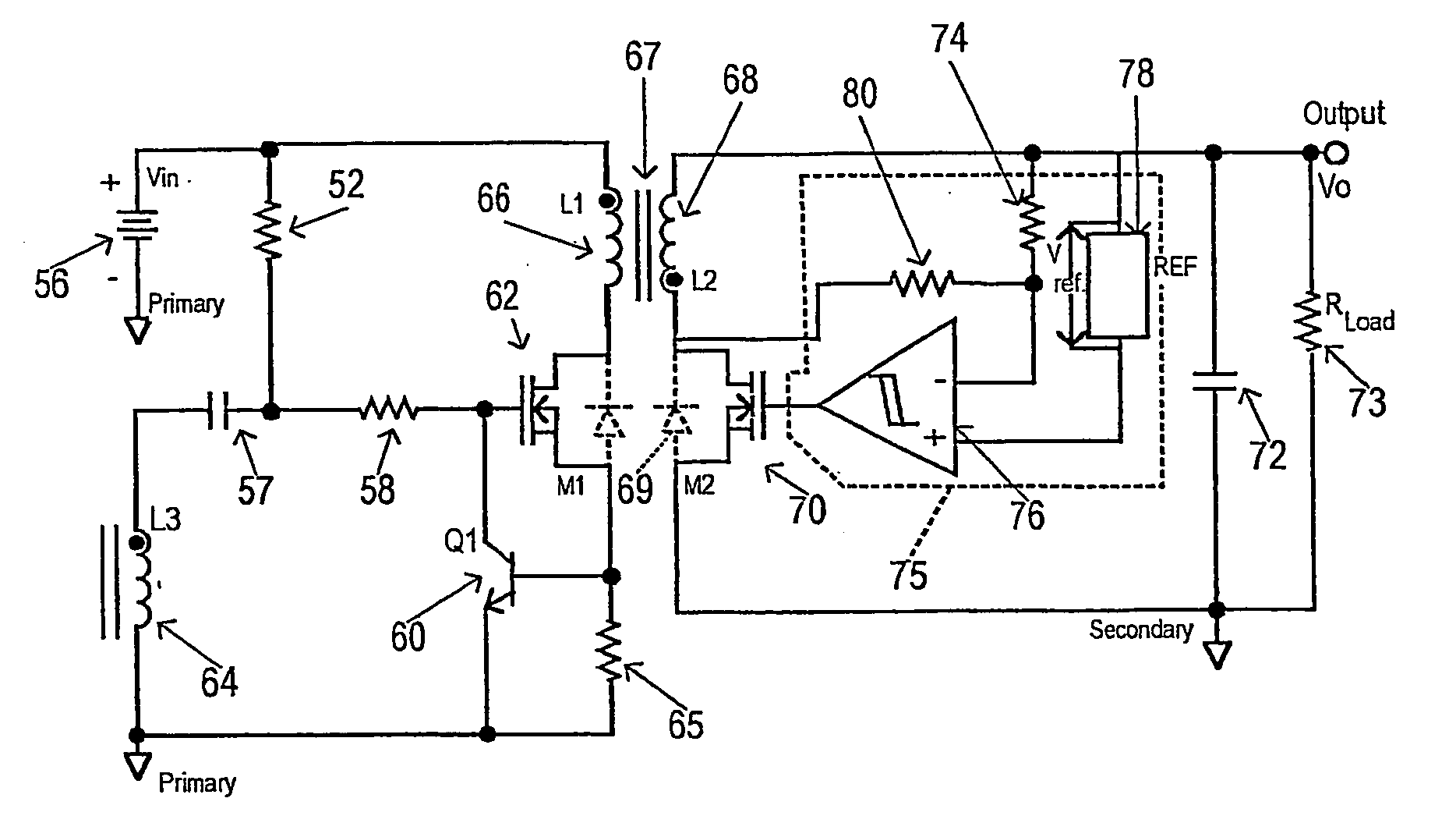
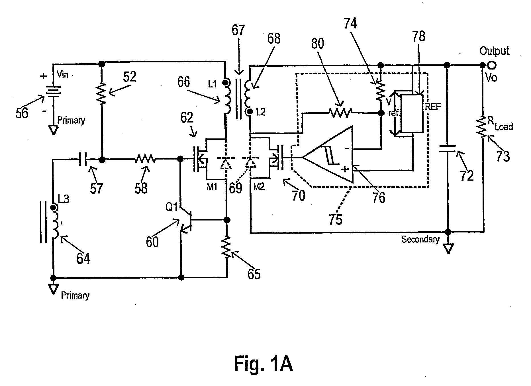
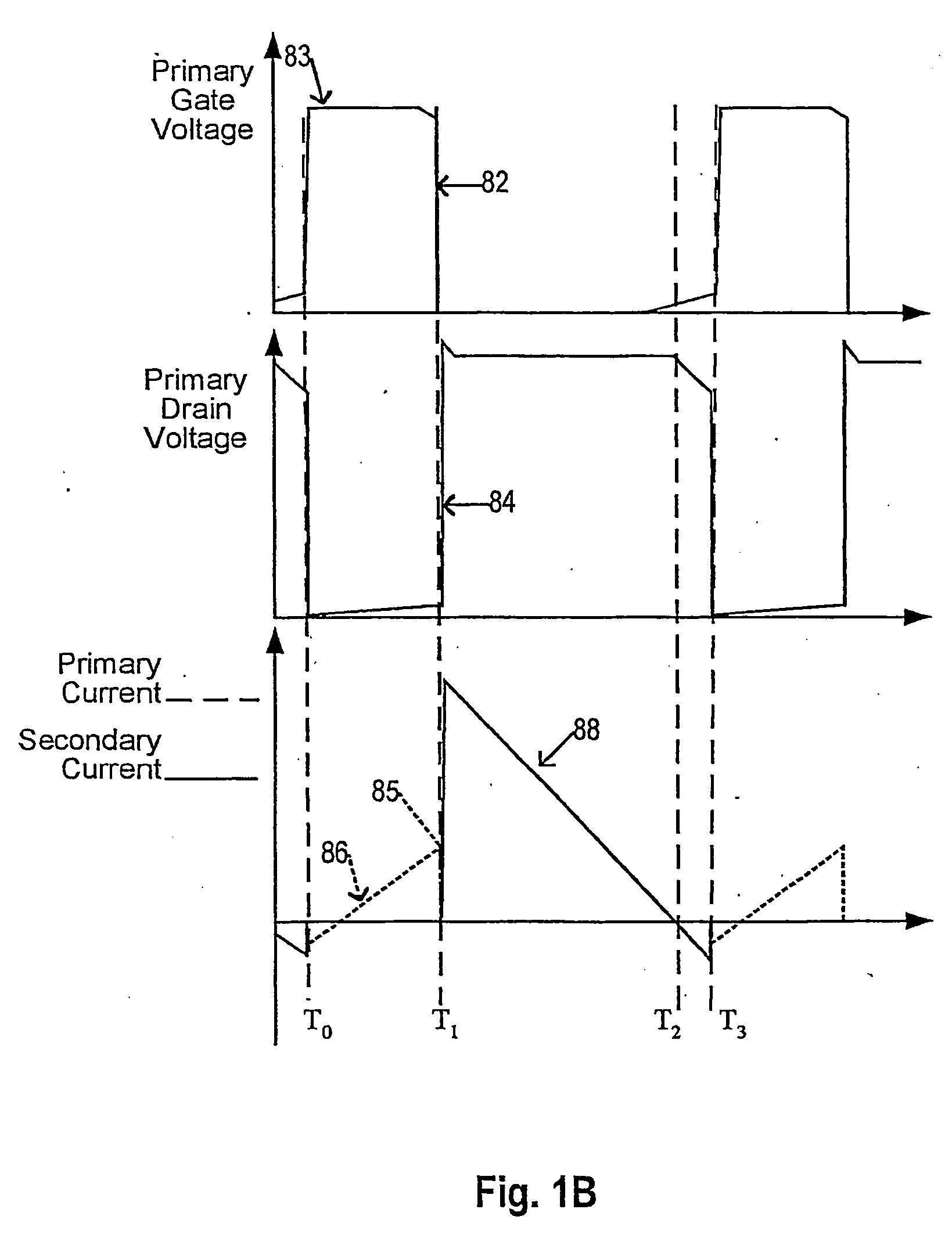
[0031] A semi-general illustration of the proposed concept applied to a self-oscillating flyback converter is illustrated in FIG. 1A with corresponding waveforms shown in FIG. 1B. Assume the converter is just powered up by applying an input voltage Vi from a DC voltage source 56. A resistor 52 charges a capacitor 57 and, through resistor 58, a gate capacitance of a MOSFET M1 acting as a primary switch 62. The MOSFET M1 turns ON when its gate threshold is reached. Voltage is applied to the primary winding 66 as the primary drain voltage 84 of M1 starts to go down at point T0 as illustrated in FIG. 1B. This in turn produces a voltage on winding a 64 which increases the primary gate voltage 82 on the MOSFET M1 further. This saturates the device. This is shown at point 83 in FIG. 1B. Primary current 86 ramps up at a rate dependent on the inductance of the primary winding 66. When the primary current 86 reaches a level, at point 85 in FIG. 1B, that produces a drop across a resistor 65 la...


PUM


Abstract

DC-DC converters such as flyback converters achieve self-regulation by communication information between primary and secondary circuits through the power transformer. Operating in accordance with a generalized concept or algorithm, the converter can be bi-directional and self-regulating. Control of the turn OFF times of semiconductor switches in first and second circuits coupled to first and second windings of the power transformer determines whether power flow is in one direction through the converter or the other direction. Turn ON timing of each semiconductor switch is when there is a reverse current through the switch and voltage across the switch is at or near zero. Turn OFF of a switch can be controlled from one or more operating parameters of the converter such as output voltage, in which case the converter's self-regulation is affected through duty cycle variation with variations in output voltage.

Description

CROSS REFERENCE TO RELATED APPLICATIONS [0001] Priority is claimed from U.S. provisional patent application Ser. No. 60 / 372,132 entitled “Soft Switching High Efficiency Flyback Converter” filed Apr. 12, 2002 in the name of Ionel D. Jitaru. That application is incorporated herein by reference.FIELD OF THE INVENTION [0002] This invention relates to DC-DC converters and more particularly to a driving / synchronization technique used to achieve zero voltage switching and regulate the output of DC-DC converters. BACKGROUND OF THE INVENTION [0003] In order to miniaturize power supplies, the control for power supplies should be simplified. Switching frequencies have been increased to reduce capacitive and magnetic elements in miniaturized power supplies. Still, in today's and future power supplies there is a need to reduce the number of components needed to control the power supply. Among the greatest challenges is communication across the isolation boundary. Several techniques exist. These ...

Claims


Application Information

Patent Timeline
Patent Type & Authority Applications(United States)
IPC IPC(8): G05F1/12H02M3/335H02M3/338
CPCH02M3/3385H02M3/33584
Inventor JITARU, IONEL D.
Owner DET INT HLDG LTD
Why Eureka
Try Eureka