
Motion adaptive noise reduction apparatus and method for video signals

a video signal and noise reduction technology, applied in the field of video processing, can solve the problems of video signal corruption, video noise is a major source of picture quality degradation, video noise is more annoying to viewers, etc., and achieve the effect of large noisy areas and optimal noise reduction

Inactive Publication Date: 2007-04-03
SAMSUNG ELECTRONICS CO LTD
View PDF4 Cites 41 Cited by
  • Summary
  • Abstract
  • Description
  • Claims
  • Application Information

AI Technical Summary

Benefits of technology

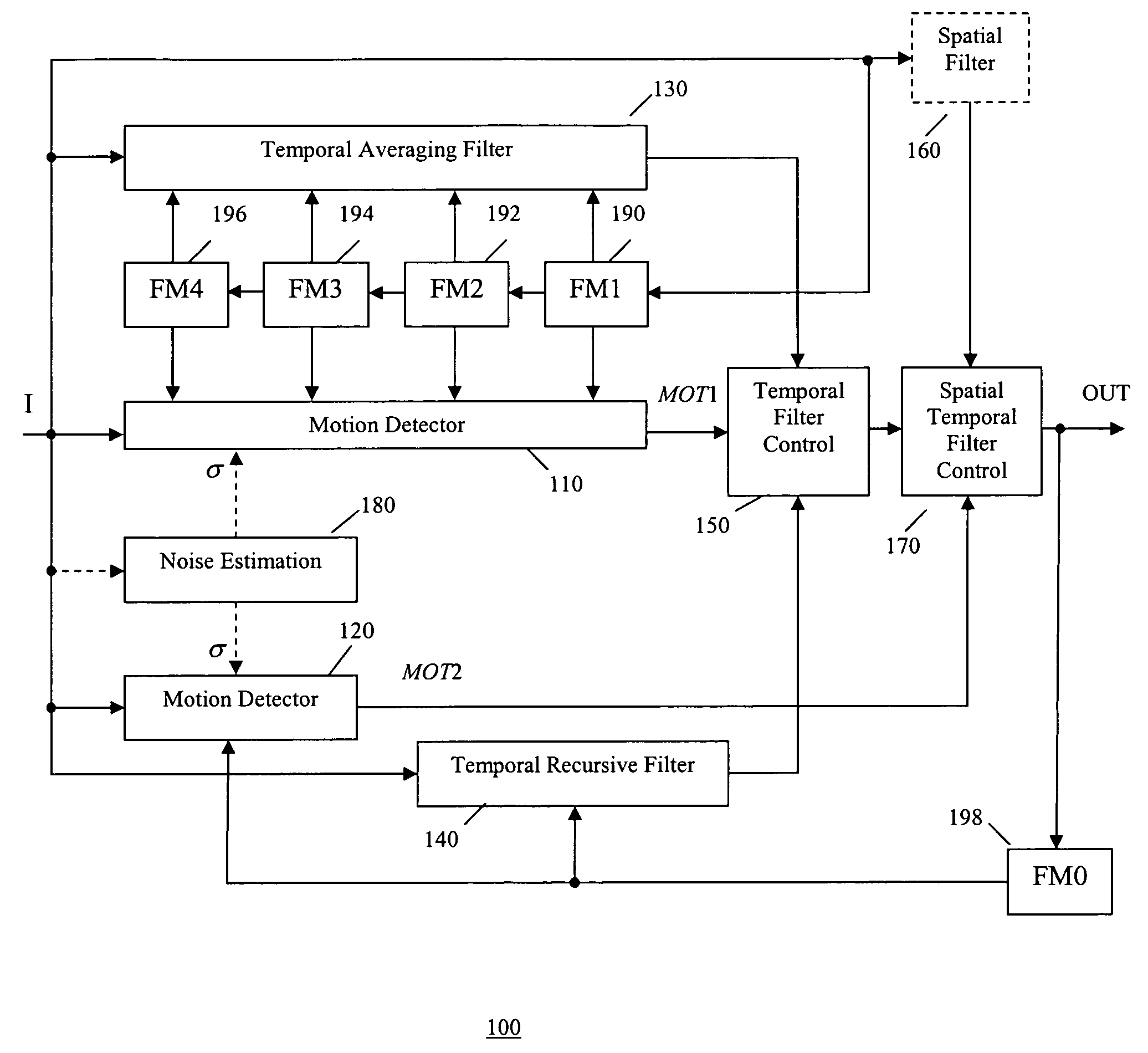
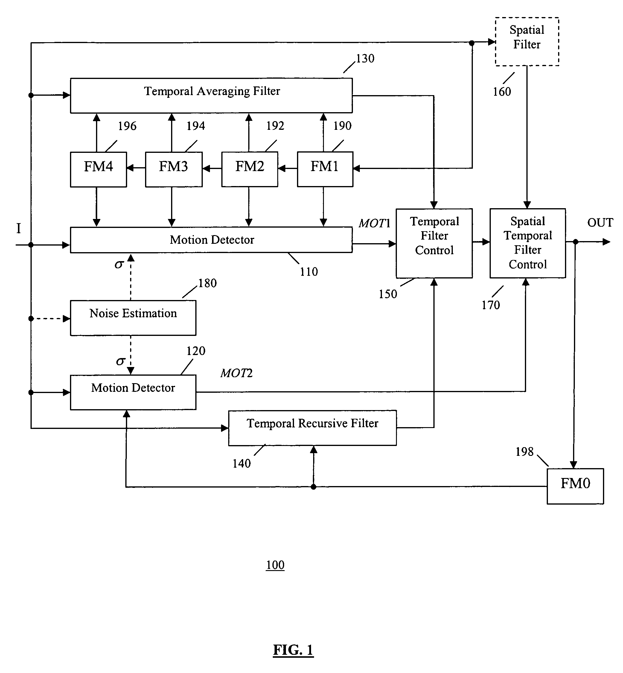
The present invention provides a video noise reduction system that uses motion detection to switch between a temporal averaging filter and a temporal recursive filter. This allows for optimal noise reduction while eliminating the creation of larger noisy areas around moving objects. The system includes two control units that use global noise statistics to detect motion and control the switching between the filters. The technical effect of this invention is improved video quality with reduced noise.

Problems solved by technology

Video signals are often corrupted by noise during acquisition or transmission processes.
Noise is a major source of degradation in picture quality.
As TV screens get ever larger, video noise has become more annoying to viewers.
Although spatial filtering is less effective than temporal filtering for video noise reduction, residual noise left by spatial filtering in moving areas is less perceptible to the human eye.
This makes the temporal averaging filter being switched off to avoid motion blurring, therefore leaving larger noisy areas around moving objects.
As memory costs continue to decrease and consumer demand for high picture quality video products increases, the first shortcoming of the temporal averaging filter has become less important, while the second shortcoming, which directly affects the picture quality, has become a more serious issue.

Method used


Image

  • Motion adaptive noise reduction apparatus and method for video signals
  • Motion adaptive noise reduction apparatus and method for video signals
  • Motion adaptive noise reduction apparatus and method for video signals

Examples


Embodiment Construction

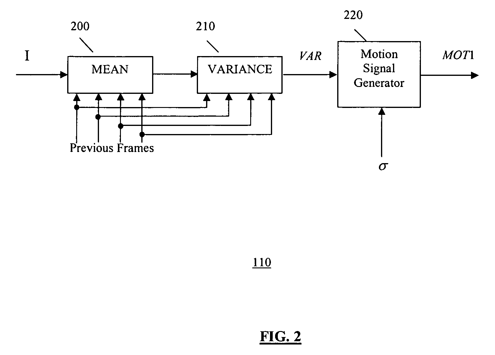
[0017]In one embodiment the present invention provides a motion adaptive video noise reduction system including a first motion detector, a second motion detector, a temporal averaging filter, a temporal recursive filter, an optional spatial filter, and two control units. The first motion detector detects content motion among current frame and multiple consecutive previous frames. The second motion detector detects content motion between the current frame and the processed preceding frame. Both motion detectors use global noise statistics, which can be calculated using a separate noise estimation unit. The temporal averaging filter uses multiple-frame averaging of current frame and previous frames. The temporal recursive filter takes two-frame averaging of current frame and processed preceding frame.

[0018]The first control unit controls the switching between the multi-frame temporal averaging filter and the two-frame temporal recursive filter based on the motion signal generated by t...


PUM


Abstract

A video noise reduction system for a set of video frames that computes a first motion signal using a current frame and multiple consecutive previous frames, computes a second motion signal using the current frame and the processed preceding frame; computes the multi-frame temporal average of the current frame and multiple consecutive previous frames; computes the recursive average of the current frame and the processed preceding frame; generates a temporal filtered signal by soft switching between the multi-frame temporal average and the recursive average based on the first motion signal; applies a spatial filter to the current frame to generate a spatial filtered signal; and combines the temporal filtered signal and the spatial filtered signal based on the second motion signal to generate a final noise reduced video output signal.

Description

FIELD OF THE INVENTION[0001]The present invention relates generally to video processing, and more particularly to noise reduction in video signals.BACKGROUND OF THE INVENTION[0002]Video signals are often corrupted by noise during acquisition or transmission processes. Noise is a major source of degradation in picture quality. As TV screens get ever larger, video noise has become more annoying to viewers. Therefore, there has been a need for high quality noise reduction systems to improve video quality.[0003]It is well known that the human eye is more sensitive to noise in still background than that in moving areas where noise is masked by the human visual system. As such, conventional motion adaptive noise reduction methods attempt to reduce video noise accordingly. In such methods, a motion detector is used to detect motion for every pixel in a video frame to generate a motion signal. The motion signal indicates the moving areas and non-moving areas within a video frame. For the no...

Claims


Application Information

Patent Timeline
Patent Type & Authority Patents(United States)
IPC IPC(8): H04N5/21G06T5/00H04N5/14
CPCH04N5/144H04N5/21G06T5/002G06T5/20G06T5/50G06T2207/10016G06T2207/20182G06T2207/20192G06T2207/20216G06T5/70
Inventor LIN, PENGKIM, YEONG-TAEG
Owner SAMSUNG ELECTRONICS CO LTD
Learn More