Two stage resonant converter

Active Publication Date: 2011-10-27
FLEXTRONICS AP LLC
View PDF24 Cites 44 Cited by
  • Summary
  • Abstract
  • Description
  • Claims
  • Application Information

AI Technical Summary

Problems solved by technology

In this and other prior art converters, the switches of the second stage work under hard switching conditions, resulting in high switching losses, and thereby affect

Method used


Image

  • Two stage resonant converter
  • Two stage resonant converter
  • Two stage resonant converter

Examples


Embodiment Construction

[0037]The following description is presented to enable one of ordinary skill in the art to make and use the invention and is provided in the context of a patent application and its requirements. Various modifications to the described embodiments will be readily apparent to those skilled in the art and the generic principles herein can be applied to other embodiments. Thus, the present invention is not intended to be limited to the embodiment shown, but is to be accorded the widest scope consistent with the principles and features described herein.

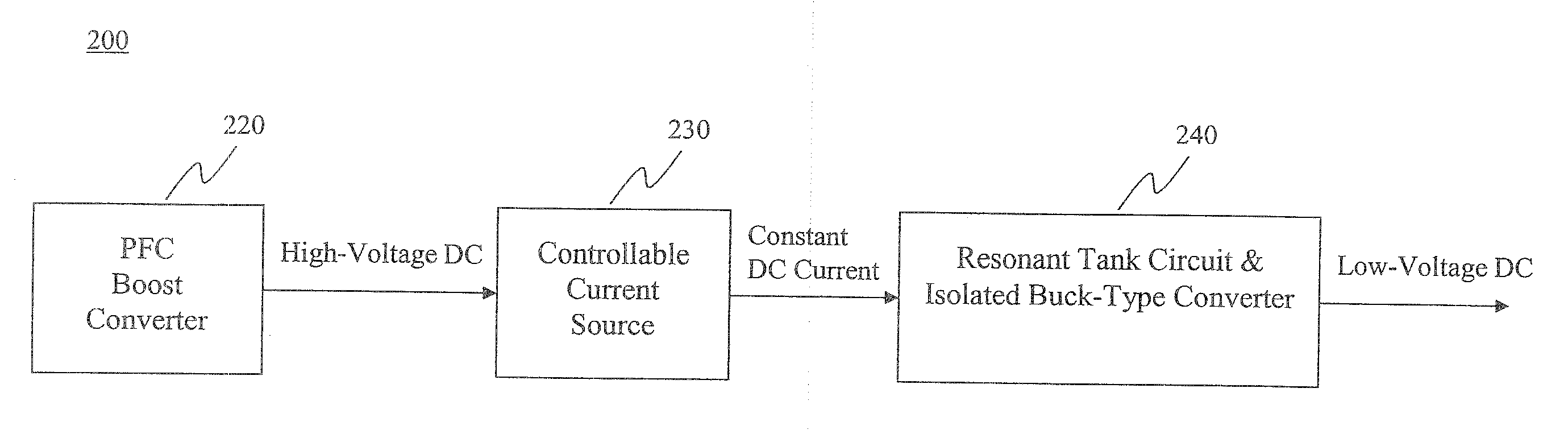
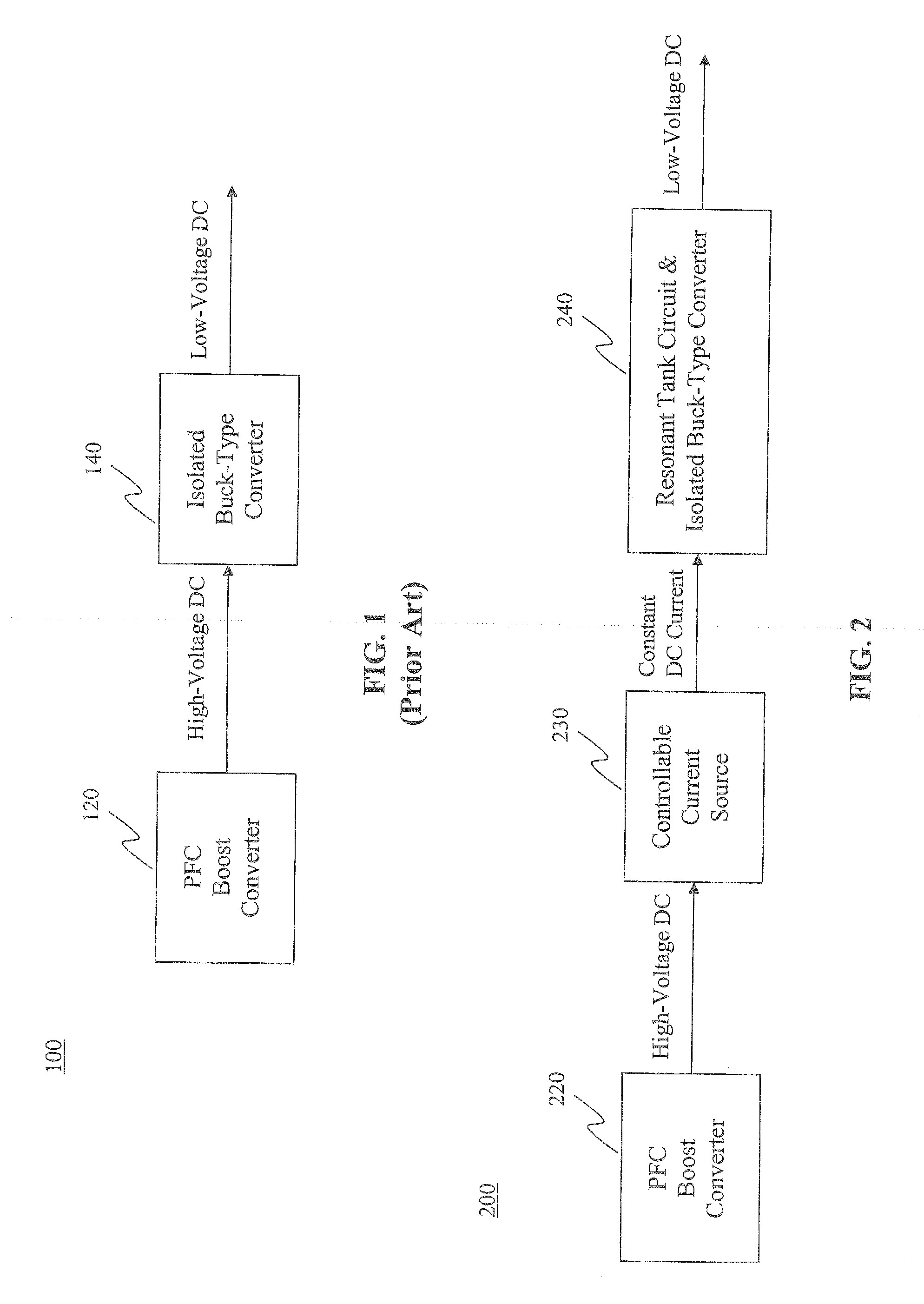
[0038]FIG. 2 is a schematic diagram of one embodiment of a two stage resonant converter 200 in accordance with the principles of the present invention. The two stage resonant converter 200 comprises a power factor correction (PFC) boost converter 220 coupled to an input of a controllable current source 230, which is coupled to a resonant tank circuit and isolated buck-type converter 240. The PFC boost converter 220 provides a high voltage D...


PUM


Abstract

A resonant converter comprising: a controllable current source; a resonant tank circuit coupled to the current source; and an isolated buck-type converter coupled to the resonant tank circuit, the isolated buck-type converter having an output, wherein the resonant tank circuit enables switches in the isolated buck-type converter to switch under soft-switching conditions. In some embodiments, the controllable current source is a switch-mode-type current source. In some embodiments, the isolated buck-type converter comprises a half-bridge converter. In some embodiments, the isolated buck-type converter comprises a full-bridge converter. In some embodiments, the isolated buck-type converter comprises a push-pull converter.

Description

FIELD OF THE INVENTION[0001]The present invention relates to the field of converter topology. More particularly, the present invention relates to a two stage resonant DC / DC converter.BACKGROUND OF THE INVENTION[0002]In DC / DC converters, a DC input voltage is converted to a lower DC output voltage. Normally, the output voltage needs to be precisely regulated and input to output isolation is necessary in order to meet safety requirements.[0003]FIG. 1 is a schematic diagram of a prior art two stage converter 100. The two stage converter 100 comprises a power factor correction (PFC) boost converter 120 and an isolated buck-type converter 140. The PFC boost converter 120 provides a high voltage DC current to the isolated buck-type converter 140. The isolated buck-type converter 140 converts the high voltage DC current into a low-voltage DC current.[0004]In this and other prior art converters, the switches of the second stage work under hard switching conditions, resulting in high switchi...

Claims


Application Information

Patent Timeline
IPC IPC(8): H02M3/337
CPCH02M1/4225H02M3/3378Y02B70/1491Y02B70/1433H02M2001/0058Y02B70/126Y02B70/10Y02P80/10H02M1/0058H02M3/28H02M3/24H02M3/22
Inventor LIU, MARTIN
Owner FLEXTRONICS AP LLC
Why Eureka
Try Eureka