Dc-dc converter

a converter and converter technology, applied in the direction of electric variable regulation, process and machine control, instruments, etc., can solve the problems of difficult to reduce circuit size and significant enhancement of efficiency, and achieve the effect of small and efficient, reducing size and weigh

Inactive Publication Date: 2010-03-11
HITACHI LTD
View PDF10 Cites 43 Cited by
  • Summary
  • Abstract
  • Description
  • Claims
  • Application Information

AI Technical Summary

Benefits of technology

[0014]The invention is a DC-DC converter having an auxiliary circuit. The auxiliary circuit includes: an auxiliary inductor magnetically coupled with a main inductor; an auxiliary switching element that stores energy in the auxiliary inductor; and an auxiliary diode that discharges the energy stored in the auxiliary inductor to a direct-current power source or the output side. The auxiliary inductor is coupled with the main inductor in the direction in which backward voltage is applied to the auxiliary diode when the main inductor discharges energy. This makes it possible to provide a small and efficient DC-DC converter that does not use a saturable inductor. In addition, a DC-DC converter that makes it possible to adopt an inductor of a relatively small capacity as an auxiliary inductor and thus significantly reduce size and weight as compared with conventional examples can be provided.

Problems solved by technology

However, loss caused by the passage of current through the series circuit of the saturable inductor and the diode exists and thus the significant enhancement of efficiency cannot be expected.
In addition, in the auxiliary resonant circuit for causing the main switching element to perform soft switching operation, two inductors, the resonant inductor and the saturable inductor, must be used as windings and this make it difficult to reduce circuit size.

Method used


Image

  • Dc-dc converter
  • Dc-dc converter
  • Dc-dc converter

Examples


first embodiment

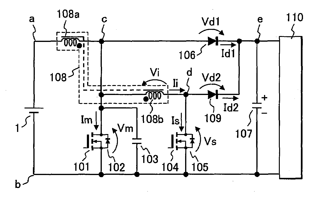
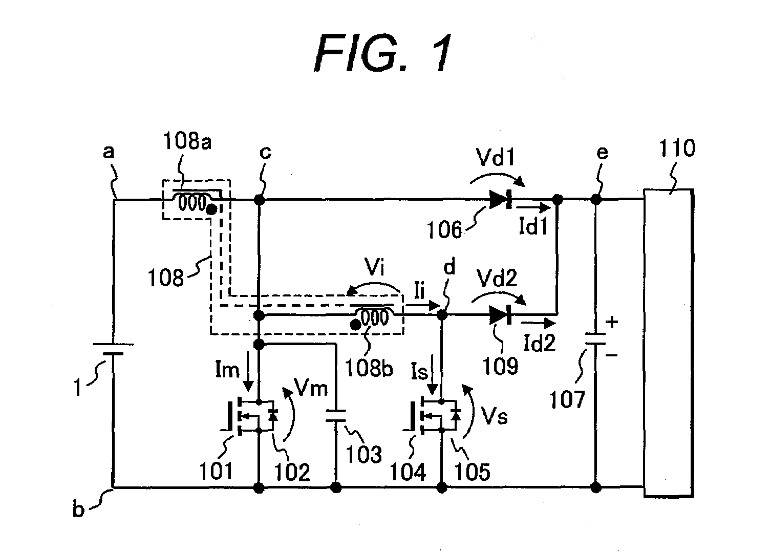
[0035]FIG. 1 is a circuitry diagram of a DC-DC converter in a first embodiment of the invention. This embodiment is a boost soft switching DC-DC converter that makes it possible to obtain an output voltage higher than input voltage.

[0036]Hereafter, description will be given to the circuitry in FIG. 1. First, a direct-current power source 1 is connected with a series circuit of a main inductor 108a and MOSFET 101 as a main switching element. This main MOSFET 101 is connected in inverse parallel with a diode 102. To take out output voltage, a series circuit of a main diode 106 and an output capacitor 107 is connected between the ends c and b of the main MOSFET 101. The ends of this output capacitor 107 are the output terminals of the DC-DC converter and are connected with a load 110.

[0037]Above is the description of the positional configuration of a common DC-DC converter and an auxiliary circuit of the invention is connected thereto.

[0038]The auxiliary circuit is obtained by: connect...

second embodiment

[0062]FIG. 5 is a circuitry diagram of a DC-DC converter having a detecting means and a control circuit in a second embodiment of the invention. This embodiment is also a boost soft switching DC-DC converter that makes it possible to obtain an output voltage higher than input voltage. In FIG. 5, the same components as in FIG. 1 will be marked with the same reference numerals and the description thereof will be omitted.

[0063]Description will be given to a difference of the DC-DC converter in FIG. 5 from that in FIG. 1. In FIG. 5, the direct-current power source 1 in FIG. 1 is comprised of: an alternating-current power source 2; a filter circuit comprised of an inductor 3 and a capacitor 4; a rectifying circuit 5; and a low-pass filter comprised of an inductor 6 and a capacitor 7. That is, the alternating-current voltage of the alternating-current power source 2 is full wave-rectified at the rectifying circuit 5 through the filter circuit comprised of the inductor 3 and the capacitor ...

third embodiment

[0069]FIG. 6 is a circuitry diagram of a DC-DC converter in a third embodiment of the invention. This embodiment is a buck soft switching DC-DC converter that makes it possible to obtain an output voltage lower than input voltage. In FIG. 6, the same components as in FIG. 1 will be marked with the same reference numerals and the description thereof will be omitted.

[0070]Description will be given to the circuitry of the DC-DC converter in FIG. 6. The direct-current power source 1 is connected with a series circuit of a main MOSFET 601 and a main diode 606; and the main MOSFET 601 is connected in inverse parallel with a diode 602 and in parallel with a snubber capacitor 603. Between the ends g and b of the main diode, a series circuit of a main inductor 607a and the output capacitor 107 is connected and the ends of the output capacitor 107 are connected to the load 110. Between the ends a and g of the main MOSFET 601, a series circuit of an auxiliary MOSFET 604 and an auxiliary induct...


PUM


Abstract

A small and efficient DC-DC converter is provided. In this DC-DC converter, passive elements such as an inductor and a capacitor can be reduced in size by reducing switching loss by a soft switching technology and increasing the drive frequency of a switching element. The DC-DC converter has a main switching element, a main diode and an auxiliary circuit that discharges the electric charges of the capacitance between the ends of the main switching element. The DC-DC converter includes an auxiliary inductor magnetically coupled with the main inductor, an auxiliary switching element that stores energy in the auxiliary inductor, and an auxiliary diode that discharges energy stored in the auxiliary inductor to the direct-current power source or the output side. The auxiliary inductor is coupled with the main inductor in the direction in which backward voltage is applied to the auxiliary diode when the main inductor discharges energy.

Description

CLAIM OF PRIORITY[0001]The present application claims priority from Japanese patent application serial No. 2008-232365 filed on Sep. 10, 2008, the content of which is hereby incorporated by reference into this applicationBACKGROUND OF THE INVENTION[0002]1. Field of the Invention[0003]The present invention relates to a DC-DC converter that converts the voltage of inputted power to a different voltage.[0004]2. Description of the Related Art[0005]The efficiency of a DC-DC converter that converts the voltage of inputted power to a desired voltage and outputs it can be enhanced by reducing switching loss by a switching technology. In conjunction therewith, such a passive element as an inductor and a capacitor can be reduced in size by increasing the drive frequency of a switching element.[0006]G. Hua et al. “Novel zero-voltage-transition PWM converters” IEEE transactions on Power electoronics, Vol. 9, pp. 213-219, 1994 (Non-patent Document 1), discloses a DC-DC converter that performs so...

Claims


Application Information

Patent Timeline
Patent Type & Authority Applications(United States)
IPC IPC(8): H02M3/335
CPCH02M3/158Y02B70/1491H02M2001/342H02M1/342Y02B70/10
Inventor OKUBO, TOSHIKAZUSHIMADA, TAKAESHOJI, HIROYUKIURUNO, JUNPEI
Owner HITACHI LTD
Why Eureka
Try Eureka