Method, system and paint for EMI suppression

Active Publication Date: 2020-02-27
MELLANOX TECHNOLOGIES LTD
View PDF18 Cites 1 Cited by
  • Summary
  • Abstract
  • Description
  • Claims
  • Application Information

AI Technical Summary

Benefits of technology

[0010]The present invention is aimed at providing easily implemented low-co

Problems solved by technology

During normal operation, electronic equipment typically generates undesirable electromagnetic energy that can interfere with the operation of other electronic equipment.
EMI emissions can be of a wide range of frequencies and may interfere with radio and wire communication.
Nearly ail digital devices that are not designed for RF communication nevertheless generate radio frequency electromagnetic waves and thus can be considered unintentional radiators.
However, in all practical applications, the enclosure is constructed of a finitely-conducting material and has some apertures and seams that inhibit the beneficial Faraday Cage effect by forming discontinuities in the conductivity of the enclosure, and through which the radiation component of the EMI may leak.
Moreover, by the known Babinet principle, the apertures can act as slot antennae, resulting in t

Method used


Image

  • Method, system and paint for EMI suppression
  • Method, system and paint for EMI suppression
  • Method, system and paint for EMI suppression

Examples


example 1

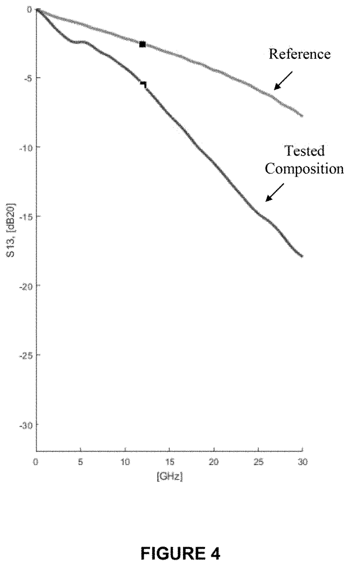
[0044]A composition comprising carbonyl iron powder, carbon powder, titanium dioxide and a conductive polymer in polyurethane matrix was tested in a microstrip test setting to study the effectiveness of the composition as EMI suppressor.

[0045]FIG. 4 presents the transmission insert on loss as function of frequency measured in the microstrip test configuration with the tested composition compared to the insertion loss measured without the composition (reference). As can be seen, the composition attenuates the RF signal at all measured frequencies and the attenuation effect increases with frequency. At frequencies above about 10 GHZ the composition attenuates radiation by more than 3 dB and above about 20 GHz by 8 dB or more.

example 2

[0046]An electromagnetic absorbing paint was prepared by mixing solvent-based polyurethane coating with carbonyl iron powder, carbon black, titanium dioxide, and polyaniline to obtain a paint of the following composition (in weight percent): n 22.4% solvent-based polyurethane, 59.2% carbonyl iron, 7.2% polyaniline, 6.3% carbon powder and 4.9% TiO2.

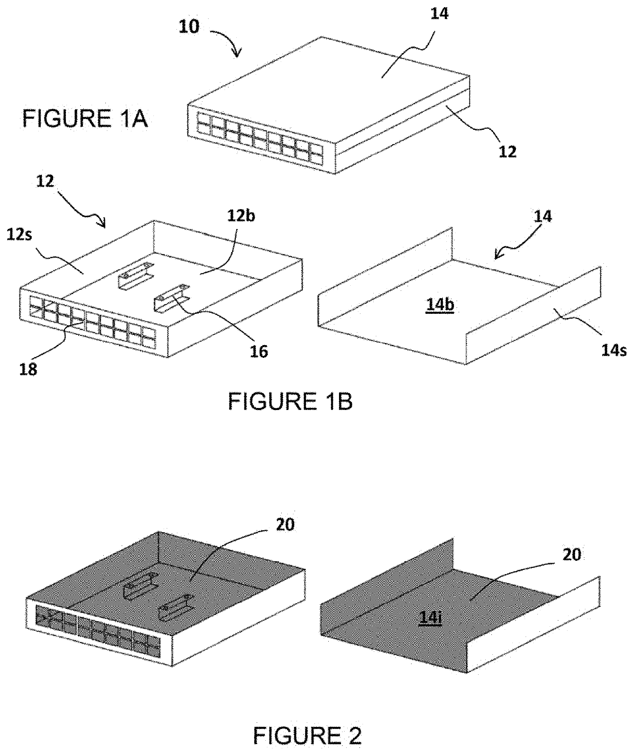
[0047]The EMI suppressing effect of the electromagnetic absorbing paint was studied on an Ethernet switch operating at 25.781 Gbps rate. The Ethernet switch was housed in an enclosure similar in structure to the housing depicted in FIG. 1, made of 1 mm thick aluminum sheet. Tests were performed for tire switch in its original enclosure (i.e., without paint), with one 0.002 inch thick dry layer of the electromagnetic absorbing paint, and with two such layers of absorbing paint.

[0048]Measurements were performed in a semi-anechoic chamber that incorporates a turntable allowing rotation of 360° and a measuring antenna. The tested switch was pl...


PUM

PropertyMeasurementUnit
Fractionaaaaaaaaaa
Fractionaaaaaaaaaa
Thicknessaaaaaaaaaa

Abstract

A method, system and paint for suppressing emission of high frequency electromagnetic radiation from an electronic system, the electronic system including at least one power supply unit, at least one printed circuit board (PCB) and at least one integrated circuit are provided. The method includes providing an electrically conductive housing configured to accommodate and encase the electronic system, the housing having an inner conductive surface, and applying a layer of an electromagnetic absorbing paint to the inner conductive surface of the housing to substantially cover the inner surface by the layer, the electromagnetic absorbing paint comprises a liquid matrix and an electromagnetic absorbing material.

Description

FIELD OF THE INVENTION[0001]The present invention generally relates to electronic equipment and, more specifically, to enclosures for electronic equipment that suppress emission of electromagnetic interference (EMI) from electronic systems.BACKGROUND OF THE INVENTION[0002]During normal operation, electronic equipment typically generates undesirable electromagnetic energy that can interfere with the operation of other electronic equipment. These disturbances, known as electromagnetic interference (EMI), are characterized by conducted emissions and radiated emissions. EMI emissions can be of a wide range of frequencies and may interfere with radio and wire communication. With the advance of computer networking and the ever increasing operating rates of electronic systems. EMI radiation frequencies may extend into tens and even hundreds of GHz.[0003]Electro Magnetic Compatibility (EMC) for electronic and electro-mechanical products is mandatory in many countries. For example, in the Un...

Claims


Application Information

Patent Timeline
IPC IPC(8): H05K9/00C09D5/32C09D175/04C09D7/61
CPCH05K9/0049C09D5/32C09D7/61C09D175/04H05K9/0083C08K3/08C08K2201/001C08K2201/01H05K9/0092C08L79/02C08K3/22C08K3/04
Inventor BADIHI, AVNERVILNER, PAVELGOZLAN, INBARPINHASOVICH, AMIR
Owner MELLANOX TECHNOLOGIES LTD
Why Eureka
Try Eureka