Wideband interferometer type polarization light beam combiner and splitter
a polarization beam and interferometer technology, applied in the field of wideband interferometer type polarization beam combiner and splitter, can solve the problem of not being able to obtain the desired properties of polarized beam combining and splitting
- Summary
- Abstract
- Description
- Claims
- Application Information
AI Technical Summary
Benefits of technology
Problems solved by technology
Method used
Image
Examples
example 1
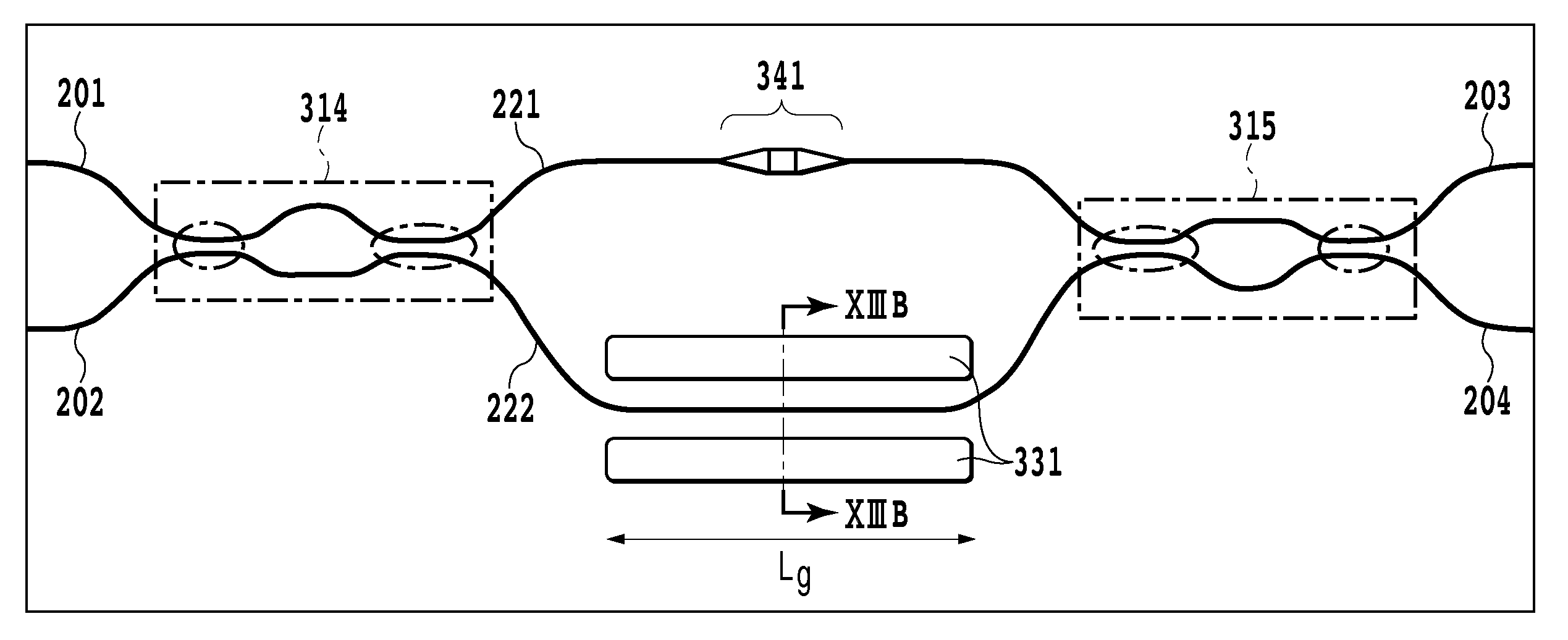
[0158]A wideband interferometer type polarization beam combiner and splitter according to example 1 is illustrated in FIG. 13A. In this example, a WINC is employed as an optical splitter and an optical coupler, and a WINC 314, serving as an optical splitter, and a WINC 315, serving as an optical coupler, are arranged symmetrically at the center of a circuit. Grooves 331 are formed in the vicinity of both sides of an optical waveguide 222 of an optical path length difference imparting unit, and differential birefringence is generated by releasing stress on the waveguide through the grooves. These grooves are called stress release grooves. Further, an element that changes the width of an optical waveguide is provided for the other optical waveguide 221 of the optical path length difference imparting unit, and is employed to generate a difference in refractive index dispersion. This element is called a width-varying waveguide 341. The means for generating differential birefringence and...
example 2
[0160]A wideband interferometer type polarization beam combiner and splitter according to example 2 is shown in FIG. 14. A difference in this example from example 1 is that a Y-branch splitter 313 is employed instead of a WINO, serving as an optical splitter, and the other arrangement is the same as that in example 1. Means for generating differential birefringence and means for generating a difference in refractive index dispersion are provided in order to satisfy equations (16) and (31).
[0161]Example numerical values will be specifically given below. The width of an optical waveguide is set as 4.5 μm. For the optical waveguides, except for the one for which either the means (a width-varying waveguide 341), for generating a difference in refractive index dispersion in an optical path length difference imparting unit, or the means (stress release grooves 331), for generating differential birefringence, is provided, an optical path length difference ΔL between an optical waveguide 22...
example 3
[0162]A wideband interferometer type polarization beam combiner and splitter according to example 3 is shown in FIG. 15A. A difference in this example from example 1 is that a plurality of means for generating differential birefringence are provided, and are located along different optical waveguides of an optical path length difference imparting unit, and the other arrangement is the same as that for example 1. In this example, as a second means for generating differential birefringence, extra optical waveguides are formed in the vicinity of both sides of an optical waveguide 221 of the optical path length difference imparting unit. This waveguide is called a birefringence adjustment waveguide 332. As shown in FIG. 15A, the birefringence adjustment waveguides 332 and a width-varying waveguide 341 may partially overlap each other. The means for generating differential birefringence and the means for generating a difference in refractive index dispersion are set to satisfy equations ...
PUM
 Abstract
Description
Claims
Application Information
 - R&D
- Intellectual Property
- Life Sciences
- Materials
- Tech Scout
- Unparalleled Data Quality
- Higher Quality Content
- 60% Fewer Hallucinations
Browse by: Latest US Patents, China's latest patents, Technical Efficacy Thesaurus, Application Domain, Technology Topic, Popular Technical Reports.
© 2025 PatSnap. All rights reserved.Legal|Privacy policy|Modern Slavery Act Transparency Statement|Sitemap|About US| Contact US: help@patsnap.com


