

Method and apparatus to release energy in a well
a well energy and well technology, applied in the direction of well/borehole valve arrangement, well/borehole/well accessories, insulation, etc., can solve the problem that many reservoirs cannot sustain the injection pressure of 3200 psi. required, the super critical water conditions of 3200 psi cannot be reached nor sustained at these depths and conditions, so as to increase the surface recovery and commercialize the desired subterranean resources
- Summary
- Abstract
- Description
- Claims
- Application Information
AI Technical Summary
Benefits of technology
Problems solved by technology
Method used
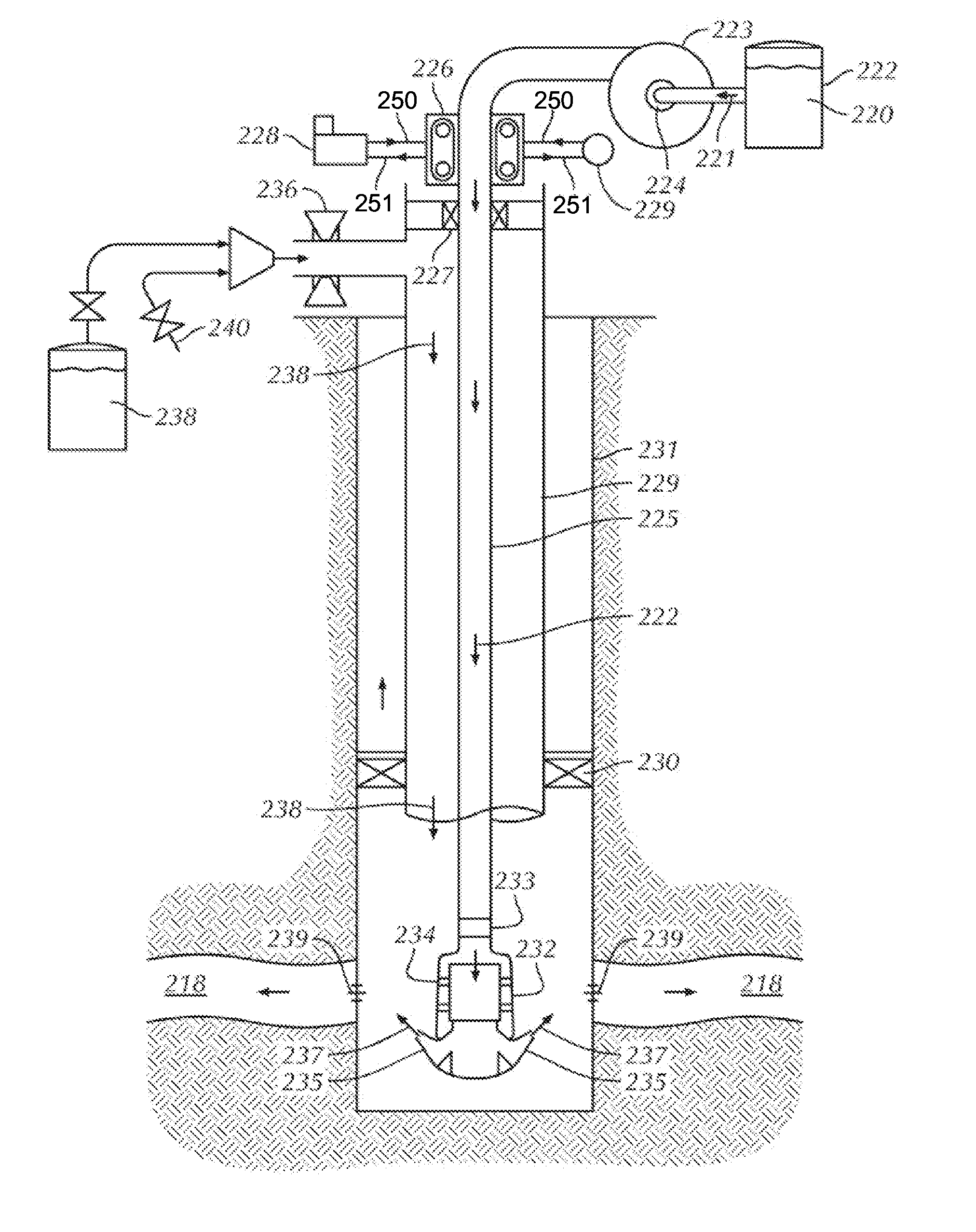
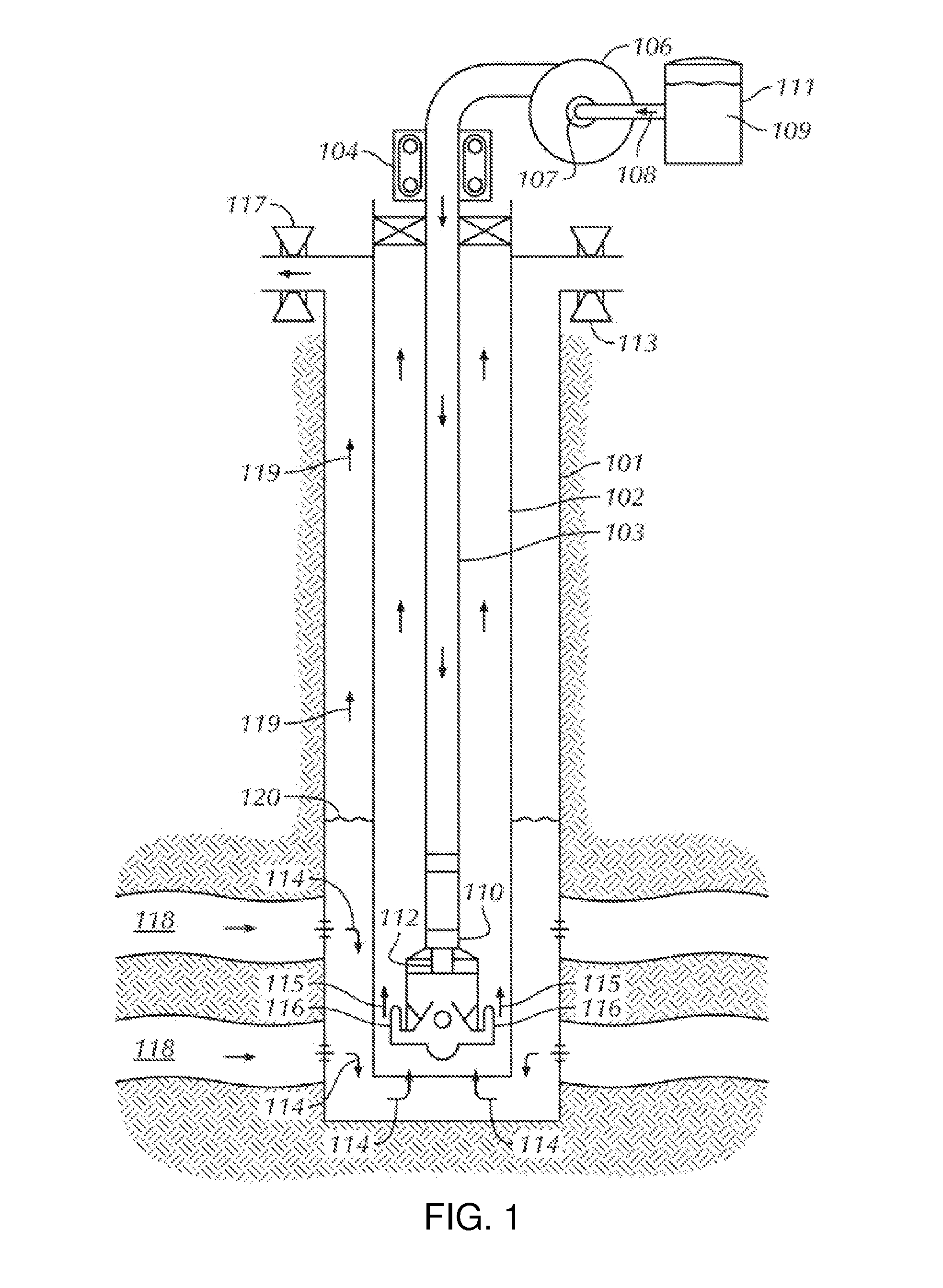
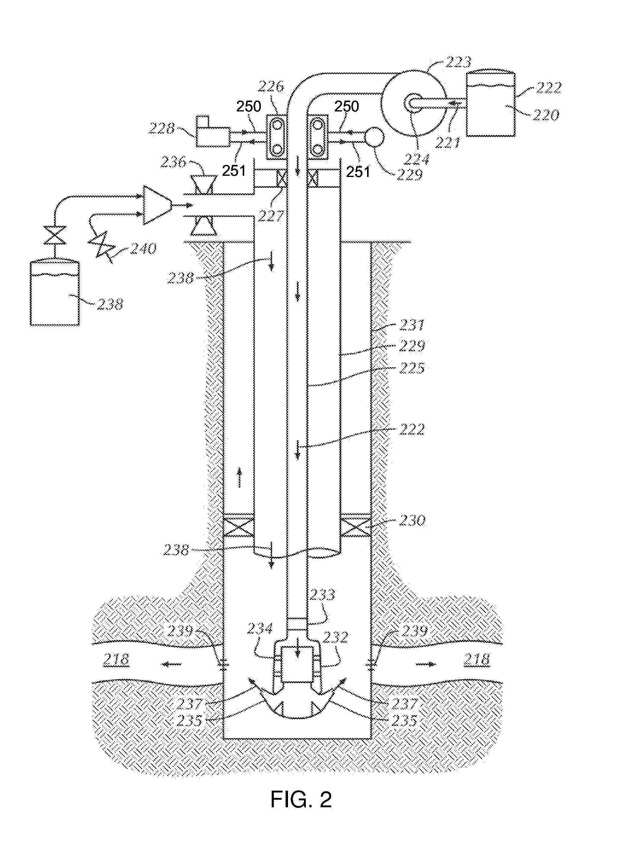
Image

Examples
Embodiment Construction
[0055]As used herein, “a” or “an” means one or more. Unless otherwise indicated, the singular contains the plural and the plural contains the singular. For example, as used herein, the term “logging tool” includes both a single logging tool and more than one logging tools arranged in any way, such as a suite of logging tools. Where the disclosure refers to “perforations” or “penetrations”, it should be understood to mean “one or more perforations” and “one or more penetrations”, respectively.
[0056]As used herein, “surface” refers to locations at or above the surface of the earth and should be understood to include those locations slightly below the surface of the earth but nevertheless substantially near the surface such that typical surface operations in hydrocarbon exploration and recovery can feasibly be performed.
[0057]As used herein, “hypergolic” refers to propellants that react immediately (i.e., spontaneously ignite) when combined together. “Non-hypergolic” refers to propella...
PUM
 Abstract
Description
Claims
Application Information