Power socket and electronic device having the same

a technology of power socket and electronic device, applied in the direction of coupling device connection, coupling protective earth/shielding arrangement, connection contact member material, etc., can solve the problems of generating potential safety hazards, complicated operation, and conventional power sockets, so as to simplify the manufacturing process of power sockets and avoid tying and sleeving. , the effect of simplifying the connection

Active Publication Date: 2014-07-29
DELTA ELECTRONICS INC
View PDF4 Cites 4 Cited by
  • Summary
  • Abstract
  • Description
  • Claims
  • Application Information

AI Technical Summary

Benefits of technology

[0017]The advantage of the invention is that a rigid connector socket takes place of the conventional flexible connecting wire between the grounding contact of the power socket and the power supply casing, which simplifies the connection between the grounding contact of the power socket and the protective grounding pin of the power supply casing, avoids the tying and sleeving and selecting the colors of the PVC tube, omits hook-welding processes, and simplifies the manufacturing process of the power socket. At the same time, the rigid connector avoids short circuit or interference with other elements, there is no need for additional protection. Further the riveting connection or the welding connection between the rigid connector and the grounding contact eliminate the potential safety hazard of the hook-welding.
is that a rigid connector socket takes place of the conventional flexible connecting wire between the grounding contact of the power socket and the power supply casing, which simplifies the connection between the grounding contact of the power socket and the protective grounding pin of the power supply casing, avoids the tying and sleeving and selecting the colors of the PVC tube, omits hook-welding processes, and simplifies the manufacturing process of the power socket. At the same time, the rigid connector avoids short circuit or interference with other elements, there is no need for additional protection. Further the riveting connection or the welding connection between the rigid connector and the grounding contact eliminate the potential safety hazard of the hook-welding.

Problems solved by technology

However, the conventional power socket has the following defects.
Due to the limitation of the hook-welding process, the connection between the first end, the U-shaped portion 24 and the grounding contact 31 is apt to break down, thereby generating potential safety hazard.
Thus, the connecting wires 51, 52 and 52 should be sleeved with PVC tubes of different colors and then bundled into a cable, which leads to complex operation and high manufacturing cost.

Method used


Image

  • Power socket and electronic device having the same
  • Power socket and electronic device having the same
  • Power socket and electronic device having the same

Examples


first embodiment

[0034]The power socket in the

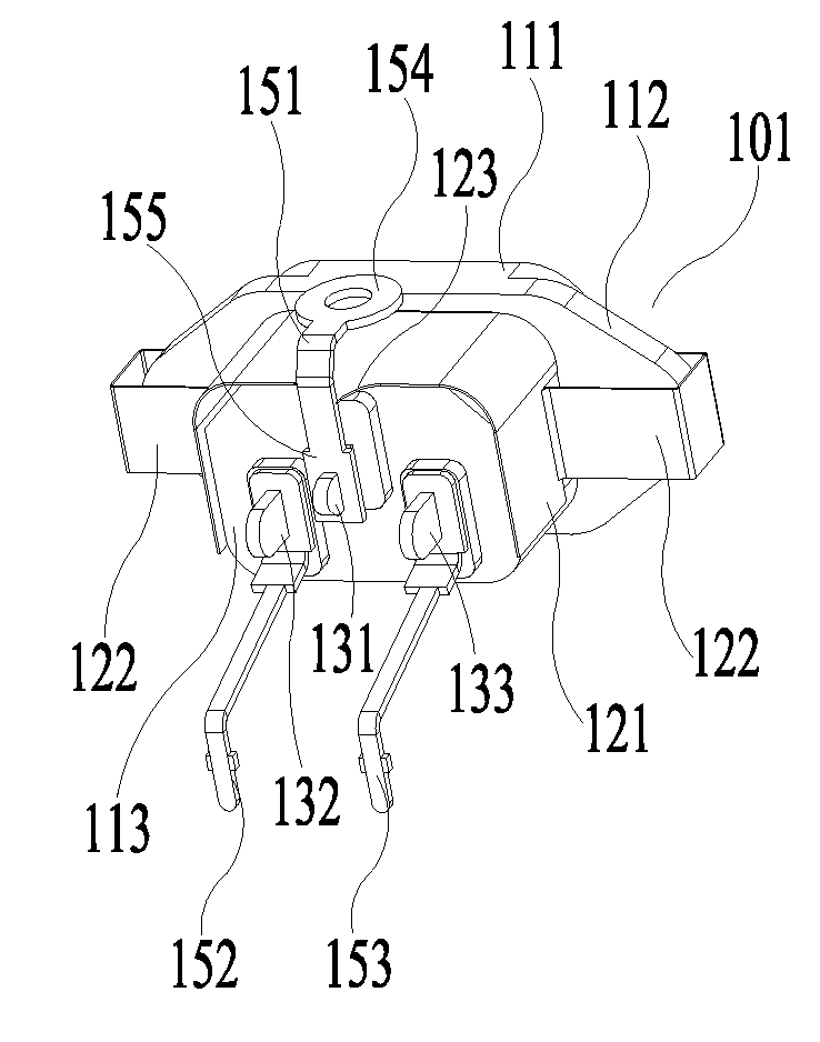
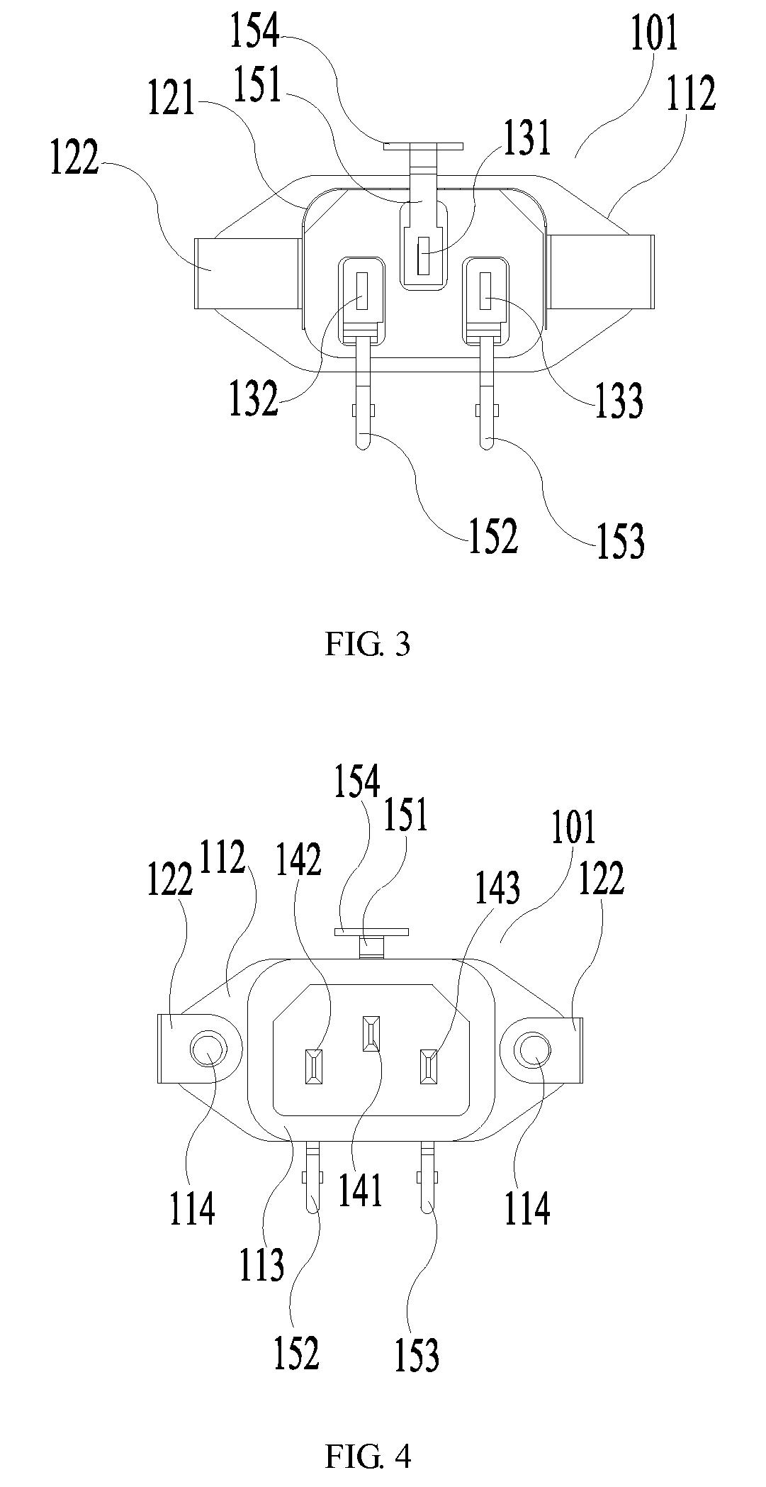
[0035]As shown in FIGS. 3 to 8, the power socket in the first embodiment of the invention includes an insulating body 101, input end contacts 141, 142 and 143, and output end contacts 131, 132 and 133. The output end contact 131 is connected to the grounding, which is also called the grounding contact 131.

[0036]The insulating body 101 includes a back plate 112, a first body 111 disposed at one side of the back plate 112 and a second body 113 disposed at the other side of the back plate 112. Screw holes 114 are defined at two ends of the back plate 112 for fixing the power socket to the power supply casing.

[0037]The input end contacts 141, 142 and 143 are disposed in the recess of the first body 112 in a triangle arrangement. The output end contacts 131, 132 and 133 protrude from the surface of the second body 113 in a triangle arrangement. Each input end contact is electrically connected to the corresponding output end contact inside the insulating body ...

second embodiment

[0045]The power socket in the invention is illustrated hereinafter.

[0046]As shown in FIG. 9, the power socket in the second embodiment includes an insulating body 201, input end contacts (not shown), output end contacts 231, 232, 233 and a shielding case 202. The output end contact 231, also called the grounding contact, is grounded. The output end contacts 232 and 233 are connected to the circuit board in the power supply through the connectors 252 and 253. The shielding case 202 includes an inverted U-shaped shielding case body 221 and two connecting portions 222 located at two sides of the shielding case body 221.

[0047]The insulating body 201 includes a back plate 212, a first body 211 and a second body 213. Screw holes 214 are defined at two ends of the back plate 212 for fixing the power socket to the power supply casing.

[0048]The power socket of the second embodiment is the same as that of the first embodiment in some parts, such as disposition form of the input end contacts a...

third embodiment

[0052]The power socket in the invention is illustrated hereinbelow.

[0053]As shown in FIG. 10, the power socket in the third embodiment includes an insulating body 301, input end contacts (not shown), output end contacts 331, 332, 333 and a shielding case 302. The output end contact 331, also called the grounding contact, is grounded. The output end contacts 332 and 333 are connected to the circuit board in the power supply through the connector 352 and 353. The shielding case 302 includes an inverted U-shaped shielding case body 321 and two connecting portions 322 located at two sides of the shielding case body 321.

[0054]The insulating body 301 includes a back plate 312, a first body 311 and a second body 313. Screw holes 314 are defined at two ends of the back plate 312 for fixing the power socket to the power supply casing.

[0055]The power socket of the third embodiment is the same as that of the first and second embodiment in some parts, such as the distribution and disposition fo...


PUM


Abstract

A power socket disposed on a power supply casing of the electronic device to provide power for the electronic device through a power cord is disclosed. The power socket includes an insulating body, three input end contacts disposed at first side of the insulating body, three output end contacts including a grounding contact disposed at second side of the insulating body, and a rigid connector connected between the grounding contact and a protective grounding pin of the power supply casing. The invention simplifies the connection between the power socket and the power supply casing, thereby simplifies the manufacturing process of the power socket and eliminating the potential safety hazard.

Description

CROSS REFERENCE TO RELATED APPLICATIONS[0001]This application claims priority to the Chinese patent application No. 201110436061.9, filed on Dec. 22, 2011, which is incorporated herein by reference in its entirety.FIELD OF THE INVENTION[0002]The invention relates to a power socket device and, more particularly, to a power socket and an electronic device having the same.DESCRIPTION OF THE RELATED ART[0003]In the related prior art, a power supply is provided in an electronic device casing for receiving the external electrical power and providing suitable current and voltage to the electronic device. A casing of the power supply is fixed to a casing of the electronic device, and the power supply socket is provided on the power supply casing and then connected to the external power supply via a power cord.[0004]As shown in FIG. 1 and FIG. 2, the conventional power socket includes an insulating body 1, an input end contact (not shown) and output end contacts 31, 32 and 33. The output end...

Claims


Application Information

Patent Timeline
Patent Type & Authority Patents(United States)
IPC IPC(8): H01R4/66H01R13/648
CPCH01R24/68H01R4/64H01R13/652H01R2103/00
Inventor KU, WUMINGHE, LEXING
Owner DELTA ELECTRONICS INC
Why Eureka
Try Eureka