
Image display device

a technology of image display and display device, which is applied in the direction of static indicating device, instruments, optical elements, etc., can solve the problems of increasing the manufacturing cost of image display device, and achieve the effect of minimizing the reduction of the luminance of the 2d imag

Active Publication Date: 2014-07-29
LG DISPLAY CO LTD
View PDF12 Cites 2 Cited by
  • Summary
  • Abstract
  • Description
  • Claims
  • Application Information

AI Technical Summary

Benefits of technology

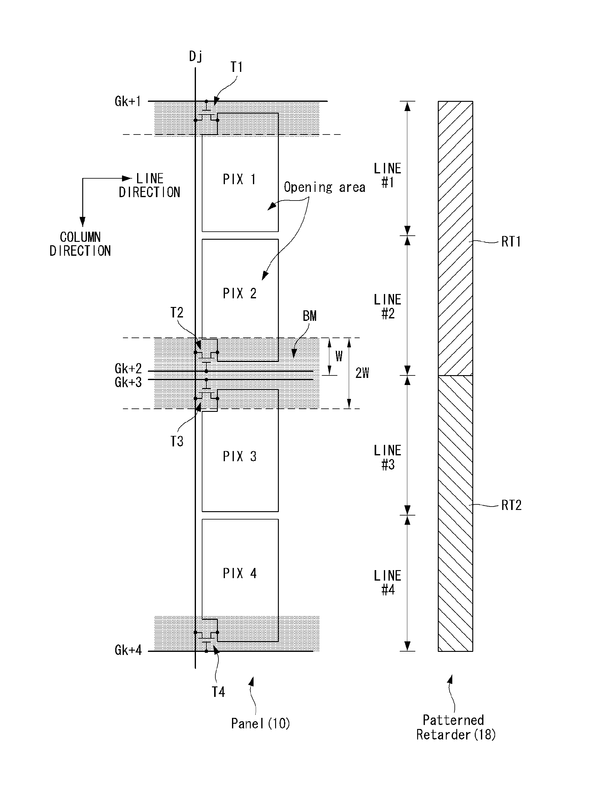
[0012]Embodiments of the invention provide an image display device capable of minimizing a reduction in a luminance of a 2D image and widening a 3D vertical viewing angle without increasing the number of light sources and adding a separate optical film.
[0016]The predetermined width of the black matrix is determined so that a 3D vertical viewing angle has a previously determined angle capable of preventing interference between the left and right images.

Problems solved by technology

Thus, the manufacturing cost of the image display devices increases.

Method used


Image

  • Image display device
  • Image display device
  • Image display device

Examples


Embodiment Construction

[0028]Reference will now be made in detail embodiments of the invention examples of which are illustrated in the accompanying drawings.

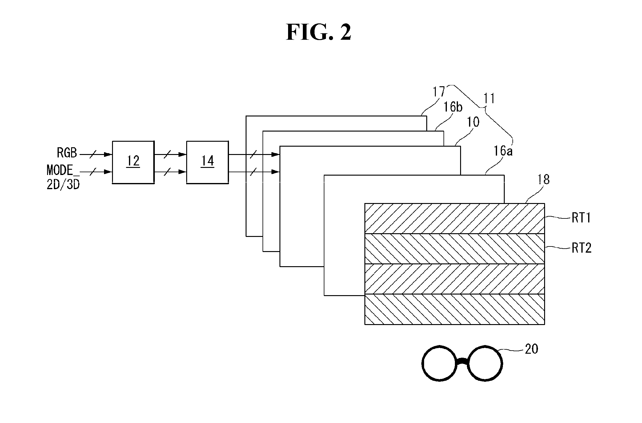
[0029]FIG. 2 illustrates an image display device according to an example embodiment of the invention.

[0030]As shown in FIG. 2, an image display device according to an example embodiment of the invention includes a display element 11, a controller 12, a panel driver 14, a patterned retarder 18, and polarization glasses 20.

[0031]The display element 11 may be implemented as a flat panel display such as a liquid crystal display (LCD), a field emission display (FED), a plasma display panel (PDP), and an electroluminescence device (EL) including an inorganic electroluminescence element and an organic light emitting diode (OLED) element. In the following description, the case where the display element 11 is implemented as the liquid crystal display will be taken as an example for the sake of brevity. The patterned retarder 18 and the polarization glasses 20...


PUM


Abstract

An image display device includes a display panel, which includes a plurality of pixels and selectively implements a 2D image and a 3D image, and a patterned retarder for dividing light from the display panel, on which the 3D image is implemented, into first and second polarization components. The display panel includes first to fourth gate lines, which cross a data line and are disposed along a column direction in the order named, first and second pixels which are disposed between the first and second gate lines to be vertically adjacent to each other, third and fourth pixels which are disposed between the third and fourth gate lines to be vertically adjacent to each other, and a black matrix spatially for separating left and right images of the 3D image from each other.

Description

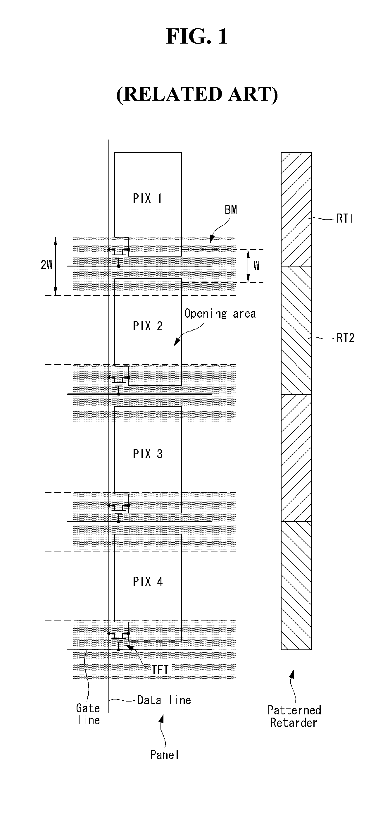
[0001]This application claims the benefit of Korean Patent Application No. 10-2010-0068133 filed on Jul. 14, 2010, which is incorporated herein by reference for all purposes as if fully set forth herein.BACKGROUND OF THE INVENTION[0002]1. Field of the Invention[0003]Embodiments of the invention relate to an image display device capable of implementing a two-dimensional plane image (hereinafter referred to as ‘2D image’) and a three-dimensional stereoscopic image (hereinafter referred to as ‘3D image’).[0004]2. Discussion of the Related Art[0005]An image display device capable of selectively implementing a 2D image and a 3D image has been recently raised due to the development of various video contents. The image display device implements the 3D image using a stereoscopic technique or an autostereoscopic technique.[0006]The stereoscopic technique, which uses a parallax image between left and right eyes of a user with a high stereoscopic effect, includes a glasses type method and a no...

Claims


Application Information

Patent Timeline
Patent Type & Authority Patents(United States)
IPC IPC(8): H04N13/04G02B27/22H04N9/47G02B30/25
CPCH04N13/0497H04N13/0404G02B27/22H04N13/0434H04N13/0452H04N13/337H04N13/356H04N13/305H04N13/398
Inventor CHAE, HEEYOUNG
Owner LG DISPLAY CO LTD
Learn More