Building and method of constructing a building

a building and construction method technology, applied in the direction of building components, structural elements, roof coverings, etc., can solve the problems of exceeding the level of thermal insulation that can be achieved using conventional construction methods without incurring substantial additional cost, and achieve the effect of reducing construction costs and high flood protection levels

Active Publication Date: 2014-08-05
THE BEATTIE PASSIVE BUILD SYST
View PDF33 Cites 14 Cited by
  • Summary
  • Abstract
  • Description
  • Claims
  • Application Information

AI Technical Summary

Benefits of technology

[0017]Advantageously, the inner and outer layers forming the void have a separation in the range 50-600 mm, preferably 200-450 mm. We have found that with currently available insulating materials this separation provides an optimum balance of insulation thickness against building cost.
[0018]Preferably, the framework is supported on discrete piles or foundation pads. This reduces the cost of construction by avoiding the need to excavate conventional foundations. As the structure of the building is very light but strong, simple piles or foundation pads have been found to provide adequate support.
[0019]A damp-proof membrane may be fitted beneath the floor structure. Advantageously, the damp-proof membrane extends at least partly up the walls of the building, preferably to a height of at least 150 mm above ground level. The membrane may be extended to a greater height if required, for flood protection. This provides a very high level of flood protection (particularly if the building is also fitted with water-tight doors and windows).

Problems solved by technology

This greatly exceeds the levels of thermal insulation that can be achieved using conventional construction methods without incurring substantial additional cost.

Method used


Image

  • Building and method of constructing a building
  • Building and method of constructing a building
  • Building and method of constructing a building

Examples


Embodiment Construction

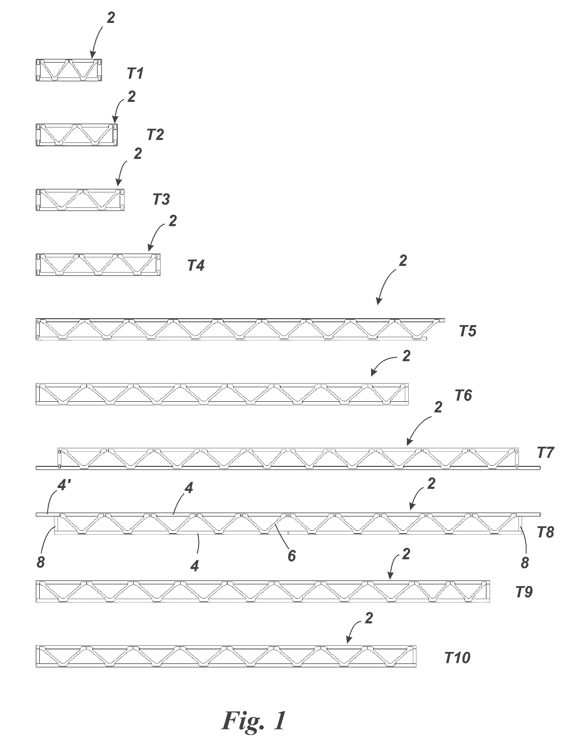
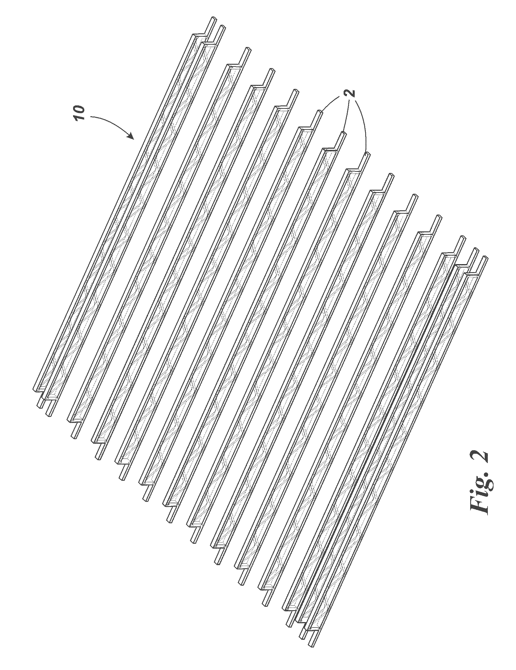
[0044]FIG. 1 shows a set of trusses 2 used in the construction method to construct a building, in this case a simple two storey house. In this example, ten types of truss 2 are shown, which vary in length and are referred to as types T1-T10. Each truss 2 includes two parallel elongate members or joists 4, which are preferably made of timber but may alternatively be made of other materials (for example steel, concrete etc). The two joists are interconnected by a series of braces 6, which may for example be made of galvanised steel and which maintain a constant separation between the joists.

[0045]In some trusses (for example types T1-T4, T6 and T9-T10) the two joists 4 are of equal length and their ends are joined by a cross-strut 8. In other trusses (for example types T5, T7 and T8), one joist is slightly longer and includes a portion 4′ at one or both ends that extends beyond the end of the other joist. In types T7 and T8, a cross-strut 8 is provided adjacent each end of the joist t...


PUM


Abstract

A method of constructing a building including erecting a plurality of truss elements to form a framework including one or more walls, a roof structure and a floor structure. Each truss element includes at least two joists and a plurality of braces that maintain the joists in a parallel arrangement, the truss elements being arranged in the framework to provide an inner joist and an outer joist. An inner covering layer and an outer covering layer are attached to the framework, thereby forming an enclosed void between the inner and outer covering layers that extends substantially continuously around the framework. An insulating material is injected into the void to form a substantially continuous insulating layer between the inner and outer layers.

Description

RELATED APPLICATIONS[0001]This application is the U.S. National Phase filing under 35 U.S.C. §371 of PCT / GB2010 / 000700, filed Apr. 7, 2010, which designated the United States and was published in English, which claims priority under 35 U.S.C. §119(a)-(d) to Great Britain Patent Application No. 0906278.7, filed Apr. 9, 2009, the content of which is incorporated herein by reference in its entirety.FIELD OF THE INVENTION[0002]The present invention relates to a building and to a method of constructing a building. In particular, but not exclusively, the invention relates to buildings such as houses, schools, offices, hospitals and similar buildings, and a method of constructing such buildings.BACKGROUND OF THE INVENTION[0003]There are numerous problems associated with conventional construction methods. One problem is that with many construction methods it is very difficult to construct a building having a very high degree of thermal insulation. Often, thermal insulation is provided by in...

Claims


Application Information

Patent Timeline
Patent Type & Authority Patents(United States)
IPC IPC(8): E04B7/04E04B5/00E04C3/02
CPCE04B1/26E02D27/14E04B1/7604E04C3/16E04D13/1675E04F15/18E04B1/18E04B1/30E04B1/76E04B1/7654E04C3/12
Inventor BEATTIE, RONALD, PETER
Owner THE BEATTIE PASSIVE BUILD SYST
Why Eureka
Try Eureka