
Method for operating a transmission device with a plurality of friction-locking and positive-locking shifting elements

a transmission device and shifting element technology, applied in the direction of instruments, transportation and packaging, transportation, etc., can solve the problems of time delay, spontaneous changes in the gradient of the transmission input speed, and cannot be taken into account to a desired extent, so as to prevent the effect of affecting the comfort of the driver

Active Publication Date: 2014-08-05
ZF FRIEDRICHSHAFEN AG
View PDF21 Cites 0 Cited by
  • Summary
  • Abstract
  • Description
  • Claims
  • Application Information

AI Technical Summary

Benefits of technology

The present invention provides a method for operating a transmission device with multiple shift elements for achieving different gear ratios. The method prevents shifting that involves form-locking shift elements which can affect driver comfort. By calculating the time period between the generation of a shift request and the engagement of the form-locking shift element or the engagement of the form-locking shift element by correcting the gradient or varying the engagement speed, the method ensures a high level of shifting comfort at a rotational speed different from the actual gradient. The method can be applied to prevent negative or positive deviations between the actual gradient and the gradient at the time of the shift request. Increasing or reducing the actuating force of the form-locking shift element helps to shorten or extend, respectively, the time period for the shifting process.

Problems solved by technology

The time delay is influenced to a considerable extent by the operating temperature of the transmission oil, inter alia, in particular when the form-locking shift elements of automatic transmissions are hydraulically actuated.
The above-described transmission devices have the problem, however, in that spontaneous changes in the gradient of the transmission input speed or the equivalent rotational speed parameter that results, for example, from a great change in the gas pedal position of a vehicle or strong braking of the vehicle by the driver cannot be taken into account to a desired extent after the time of the shift request to engage a form-locking shift element.

Method used


Image

  • Method for operating a transmission device with a plurality of friction-locking and positive-locking shifting elements
  • Method for operating a transmission device with a plurality of friction-locking and positive-locking shifting elements
  • Method for operating a transmission device with a plurality of friction-locking and positive-locking shifting elements

Examples


Embodiment Construction

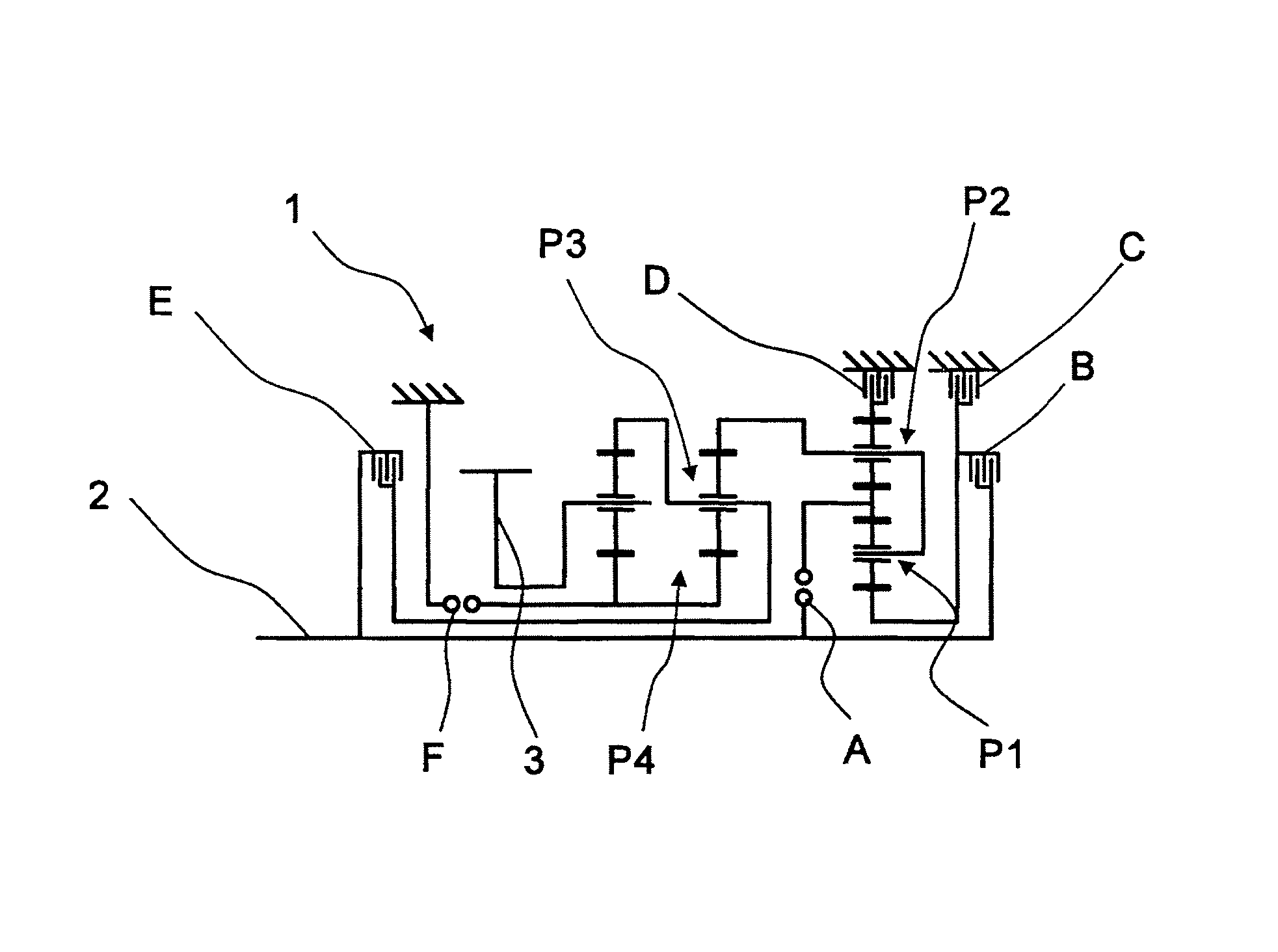
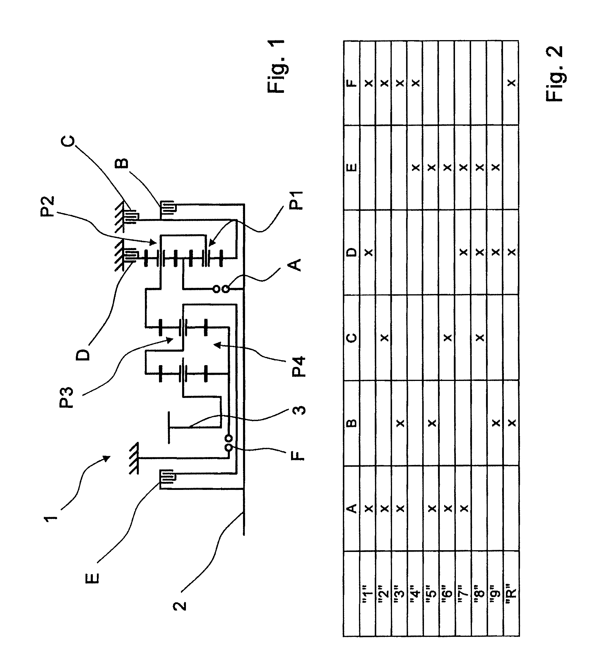
[0027]FIG. 1 shows a gearwheel pattern of a transmission device 1 or a multi-stage transmission, which is basically known from the unpublished German patent application DE 10 2008 000 429.4 which belongs to the applicant. The transmission device 1 comprises a drive shaft 2 and an output shaft 3 which, in the installed state in a vehicle, is connected to an output drive of the vehicle, while the drive shaft 2 is operatively connected to a drive motor.

[0028]The transmission device 1 also comprises four planetary gear sets P1 to P4, wherein the first and second planetary gear sets P1, P2, which are preferably in the form of minus planetary gear sets, form a shiftable, input-side gear set, while the third and fourth planetary gear sets P3, P4 are the main gear set. The transmission device 1 also comprises six shift elements A to F, of which shift elements C, D and F are designed as brakes, and the shift elements A, B and E are designed as shifting clutches.

[0029]Using the shift elements...


PUM


Abstract

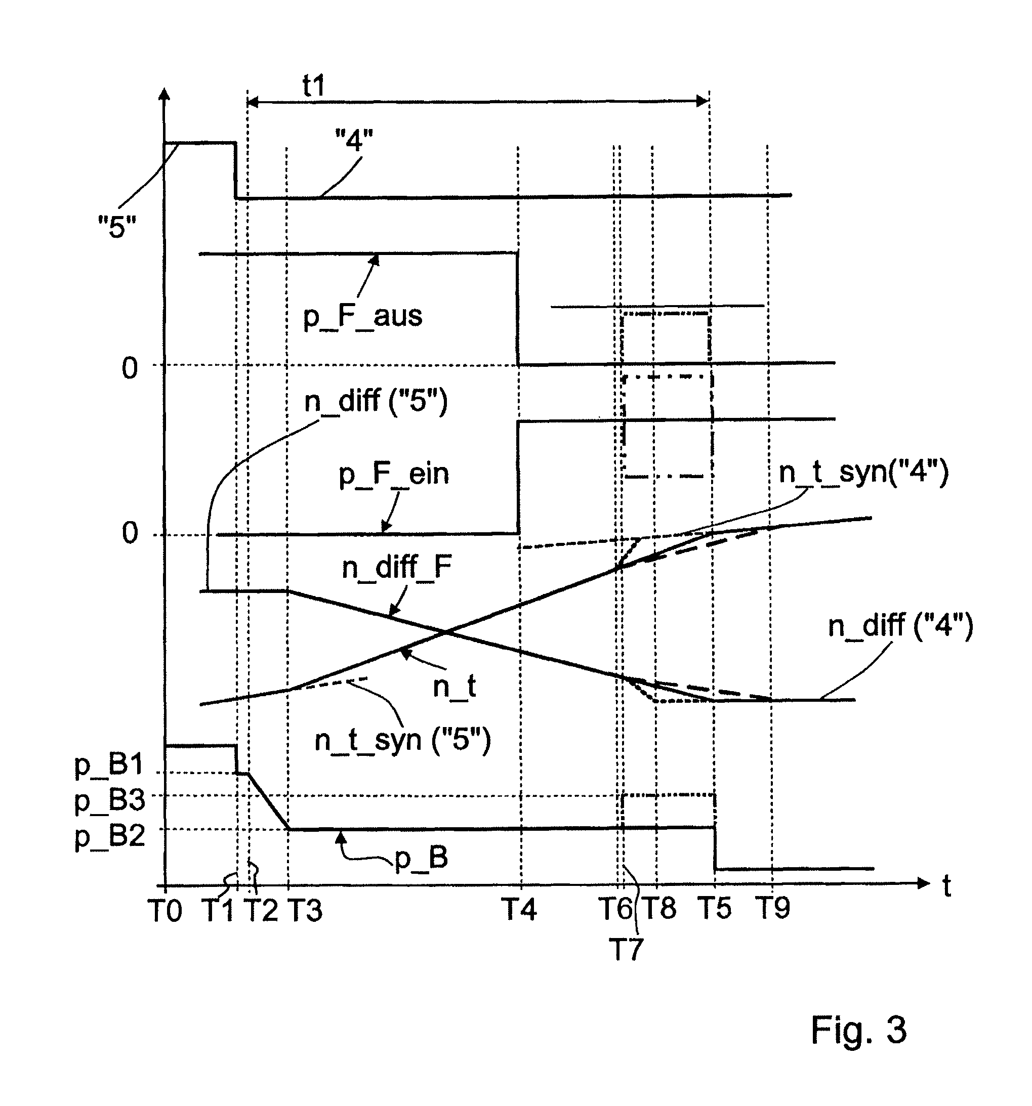
A method of operating a transmission device comprising friction-locking and form-locking shift elements for obtaining different gear ratios. A shift request for engaging a shift element undergoes a time delay dependent upon an operating state prior to a time of engagement of the shift element. A rotational speed differential between halves of the shift element lies within a rotational speed differential window required for the engagement procedure is assigned to the time of engagement. A gradient of the transmission input speed is ascertained at the time of the shift request, and the actual gradient is subsequently monitored and compared with the gradient that existed at the time of the shift request. If an absolute deviation greater than a threshold value is ascertained, the time delay is changed or an actuation of another shift element to be disengaged is varied such that the deviation is reduced below the threshold value.

Description

[0001]This application is a National Stage completion of PCT / EP2010 / 054313 filed Mar. 31, 2010, which claims priority from German patent application serial no. 10 2009 002 203.1 filed Apr. 6, 2009.FIELD OF THE INVENTION[0002]The invention relates to a method for operating a transmission device comprising a plurality of friction-locking and form-locking shift elements.BACKGROUND OF THE INVENTION[0003]In automatic transmissions known from practical applications, which comprise friction-locking shift elements and form-locking shift elements for obtaining different gear ratios, the shift command for engaging a form-locking connection by applying force is triggered by a transmission control or transmission software implemented in the transmission control with a certain time delay before the synchronization point of the form-locking shift element is reached.[0004]The time delay is influenced to a considerable extent by the operating temperature of the transmission oil, inter alia, in part...

Claims


Application Information

Patent Timeline
Patent Type & Authority Patents(United States)
IPC IPC(8): F16H3/44F16H3/66F16H59/42F16H61/04F16H61/08F16H61/686
CPCF16H3/666F16H61/0403F16H61/08F16H61/0437F16H61/686F16H2003/442F16H2061/0474F16H2200/2064F16H2200/2046F16H2200/2012F16H2200/0065F16H2059/425F16H2200/2094F16H61/04
Inventor ARNOLD, JORGHERBETH, VALENTINEMIHATSCH, GEORG
Owner ZF FRIEDRICHSHAFEN AG
Learn More