Mounting sleeve for mounting a ring member on a shaft and a bearing assembly incorporating such a mounting sleeve

a technology for mounting sleeves and bearings, which is applied in the direction of mechanical devices, couplings, rigid support of bearings, etc., can solve the problems of increasing the cost of bearings, reducing the ability of bearings to accommodate axial loads, and displaced inner race rings of bearings, so as to increase the ability to accommodate and increase the axial load

Active Publication Date: 2014-08-12
AB SKF
View PDF14 Cites 2 Cited by
  • Summary
  • Abstract
  • Description
  • Claims
  • Application Information

AI Technical Summary

Benefits of technology

[0010]Therefore a purpose of the present invention is to propose a mounting sleeve increasing the ability to accommodate and transfer axial load, and this has been achieved with a mounting sleeve having a tapering inner bore on a cylindrical shaft, the mounting sleeve comprising a sleeve having an inner cylindrical envelope surface and a friction increasing treatment on the inner surface so as to increase axial loading transferable by the sleeve between the ring and the shaft while remaining generally axially fixed on the shaft.

Problems solved by technology

As a smaller bearing (motivated from the down-sizing aspect) has a smaller nominal diameter or smaller width or both, a consequence in this respect is that the ability of the bearing to accommodate axial load is decreasing, i.e. there will be a risk that the bearing inner race ring will be displaced from its position, which is not acceptable for a locating bearing.
Therefore the parameters of the mounting sleeve will be the determining factor, and it should be necessary to increase the size of the bearing depending on the sleeve, which will give a more expensive bearing, and the possibilities of down-sizing the bearing assembly will be lost.
A possible manner of compensating this would be to increase the driving up (expansion) of the bearing inner race ring, but this in turn would give the negative consequence of an increase of the ring tension tangentially, resulting in a reduced fatigue endurance for the bearing.

Method used


Image

  • Mounting sleeve for mounting a ring member on a shaft and a bearing assembly incorporating such a mounting sleeve
  • Mounting sleeve for mounting a ring member on a shaft and a bearing assembly incorporating such a mounting sleeve
  • Mounting sleeve for mounting a ring member on a shaft and a bearing assembly incorporating such a mounting sleeve

Examples


Embodiment Construction

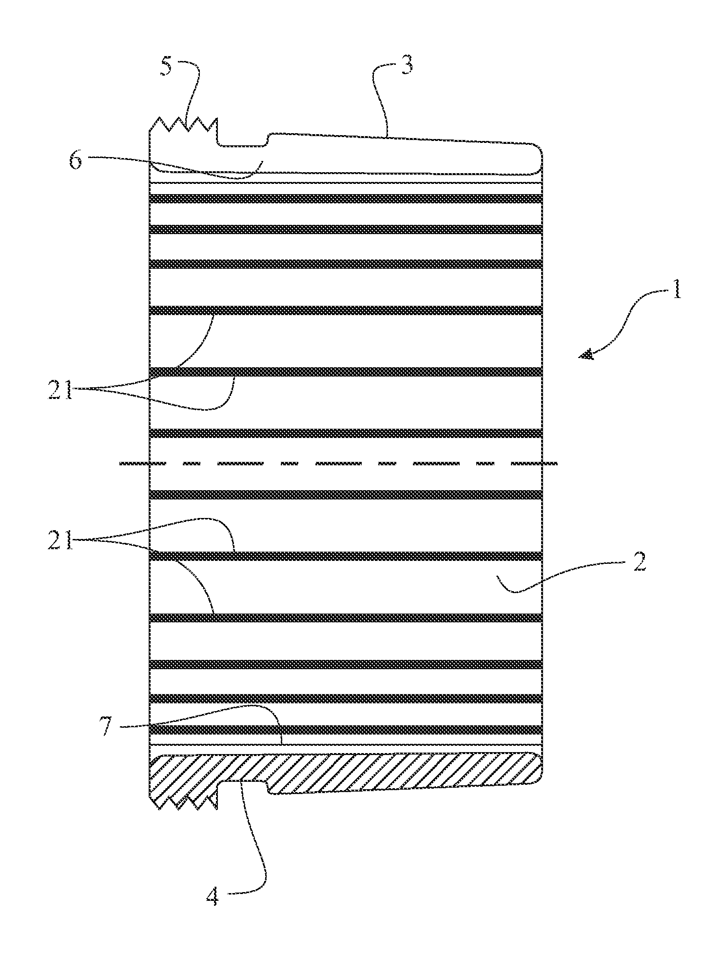
[0016]FIG. 1 shows a cross-section of a mounting sleeve 1, in this embodiment being designed as a withdrawal sleeve, primarily intended for mounting and dismounting of bearing race rings, even if its use is not limited to mounting of rings for bearings.

[0017]The mounting sleeve 1 is thin-walled and has a substantially cylindrical inner envelope surface 2 and a slightly tapering outer envelope surface 3. Adjacent one axial end of the sleeve 1 there is arranged a circumferentially groove 4 and a threaded end portion 5. The sleeve 1 also is provided with an axially extending slot 6.

[0018]For increasing the ability to transfer axial force without slipping axially, the inner envelope surface 2 of the sleeve 1 has been subjected to friction increasing treatment in order to increase the Famax-value, in spite of reduced contact surface for the inner envelope surface 2 of the mounting sleeve 1 against a (not shown) shaft. For achieving such increased friction, the inner envelope surface 2 of...


PUM


Abstract

The present invention refers to a mounting sleeve (1) for mounting a ring having a tapering inner bore on a cylindrical shaft, wherein the mounting sleeve has a cylindrical inner envelope surface, wherein the inner surface of the mounting sleeve has an increased friction coefficient, for giving an increased ability to the mounting sleeve to transfer axial load, without sliding along the surface of the shaft.

Description

BACKGROUND OF THE INVENTION[0001]The present invention refers to mounting of ring members on a shaft, and particularly and particularly to a mounting sleeve for mounting a bearing race ring on a shaft in order to give an improved ability of supporting axial load without slipping on the shaft. The invention also refers to a bearing assembly incorporating such a mounting sleeve.[0002]In recent years, the load carrying capacity of rolling bearings has steadily increased due to improvements of internal bearing geometry, heat treatment and materials. As a consequence thereof, it is today possible to use bearings of smaller size for the same load as earlier required larger bearings, or alternatively, bearings of a certain size are today used for higher loads. A commonly used expression for this development is “down-sizing”.[0003]As structural elements for fitting rolling bearings on shafts it is often used adapter sleeves, withdrawal sleeves or splined sleeves. All those sleeves are compa...

Claims


Application Information

Patent Timeline
Patent Type & Authority Patents(United States)
IPC IPC(8): F16C35/063
CPCF16B2/005F16C19/38F16C35/073F16D1/096F16C23/086F16C2300/02F16C2226/16F16C2240/70F16B3/06F16D1/097
Inventor WENDEBERG, HANSLEANDER, HAKAN
Owner AB SKF
Why Eureka
Try Eureka