Corn cob conveying and cleaning system using induction and air flow from a harvester for separating and spreading light crop residue

a technology of conveying system and corn cob, which is applied in the direction of mowers, agricultural tools and machines, etc., can solve the problems of insufficient utilization of available air flow discharged from the cleaning, reduced soil nutrient content of cob collection, and large volume of air flow, so as to facilitate the separation of lighter elements and increase the mass

Inactive Publication Date: 2014-08-12
BLUE LEAF I P INC
View PDF44 Cites 8 Cited by
  • Summary
  • Abstract
  • Description
  • Claims
  • Application Information

AI Technical Summary

Benefits of technology

[0012]As another advantage of the invention, a conventional crop residue spreader can be utilized as the residue separating apparatus, and in this role, can also be utilized for spreading the separated residue over a field. As another advantage, when not used for residue separation, the separating apparatus can be configured for use in the traditional crop spreading role.
[0013]As a further advantage, the separating apparatus can be utilized in a variety of positions and orientations, as best suited for a particular application. As an example, the separating apparatus can be positioned such that the inlet opening faces generally forwardly toward the discharge outlet, at least partially in the path of the cleaning system air flow, but not directly in the path of the residue flow. In particular, in this configuration, a deflector plate within the rear enclosure of the harvester will be positioned and oriented to direct the residue flow, which here is airborne, downwardly and forwardly of the inlet opening, with the air flow directed more horizontally and rearwardly through the residue flow. This is advantageous, as the air flow tends to break up the residue flow at least somewhat as it is airborne, which facilitates separation of the lighter elements from the cobs. The induction generated by the impellers of the separating apparatus will create a low or negative pressure condition forwardly of the inlet opening or openings, toward which the air flow will go so as to flow into the inlet opening or openings, with sufficient power to separate the lighter elements of the residue from the cobs. The cobs, which have more downward momentum due to their greater mass, will then continue along the original downward flow path.
[0014]As another example, residue separating apparatus can be positioned such that the inlet opening or openings will face generally downwardly toward the conveyor, and a portion may face the air flow, but will be above the bulk of the residue flow. In this configuration, the housing of the residue separating apparatus and the conveyor extend generally convergingly toward the rear, such that the space therebetween through which the crop residue is conveyed and the air flows, will gradually decrease in extent, with the result that at least a portion of the air flow will redirect toward the inlet or inlets. Appropriate sheeting or curtains can be provided around all or a portion of this area to reduce air which can escape in other directions to facilitate this. This flow, combined with the induction of the impeller or impellers, will act to lift and separate the lighter elements of residue from the heavier cobs, and carry them into the housing, while the cobs continue along the conveyor.
[0015]As another example, the residue separating apparatus can be positioned such that the inlet opening or openings are oriented at one or more intermediate positions between the position facing the discharge outlet and the downward orientation, partially or fully in a path of the air flow exiting the harvester. In this configuration, the lighter elements cab be drawn and separated from the heavier cobs just before or as they land and settle on the conveyor, and while they are still airborne at least somewhat, but in a manner such that the cobs are not inducted into the separating apparatus.
[0016]As another preferred aspect of the invention, the residue separating apparatus can comprise two of the impellers configured for counter rotation in a side by side relationship, e.g., so as to extend across the width of the conveyor or discharge outlet, and can direct the residue outwardly toward the sides.
[0017]As an optional feature of the invention, the residue separating apparatus is adjustably movable relative to the harvester and the conveyor, for adjusting a position of the at least one inlet opening, and so as to be configurable when the conveyor is absent, for use in a conventional manner as a spreader for receiving a flow of crop residue directly from the harvester and spreading the crop residue over a field. This enables adjusting the system for different conditions, e.g., air flow levels, velocity, etc., and residue amounts, consistency, and the like.

Problems solved by technology

There is also concern by some that cob collection may reduce soil nutrient content.
An observed shortcoming of the above referenced known cob conveying and cleaning systems, is a lack of utilization of available air flow discharged from the cleaning system of a harvester, which air flow can be quite voluminous.
The known systems also do not use existing residue spreaders in a residue cleaning or separating capacity.

Method used


Image

  • Corn cob conveying and cleaning system using induction and air flow from a harvester for separating and spreading light crop residue
  • Corn cob conveying and cleaning system using induction and air flow from a harvester for separating and spreading light crop residue
  • Corn cob conveying and cleaning system using induction and air flow from a harvester for separating and spreading light crop residue

Examples


Embodiment Construction

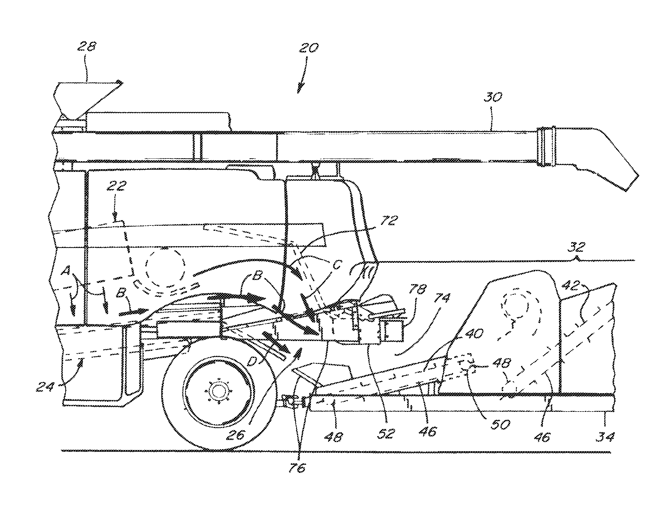
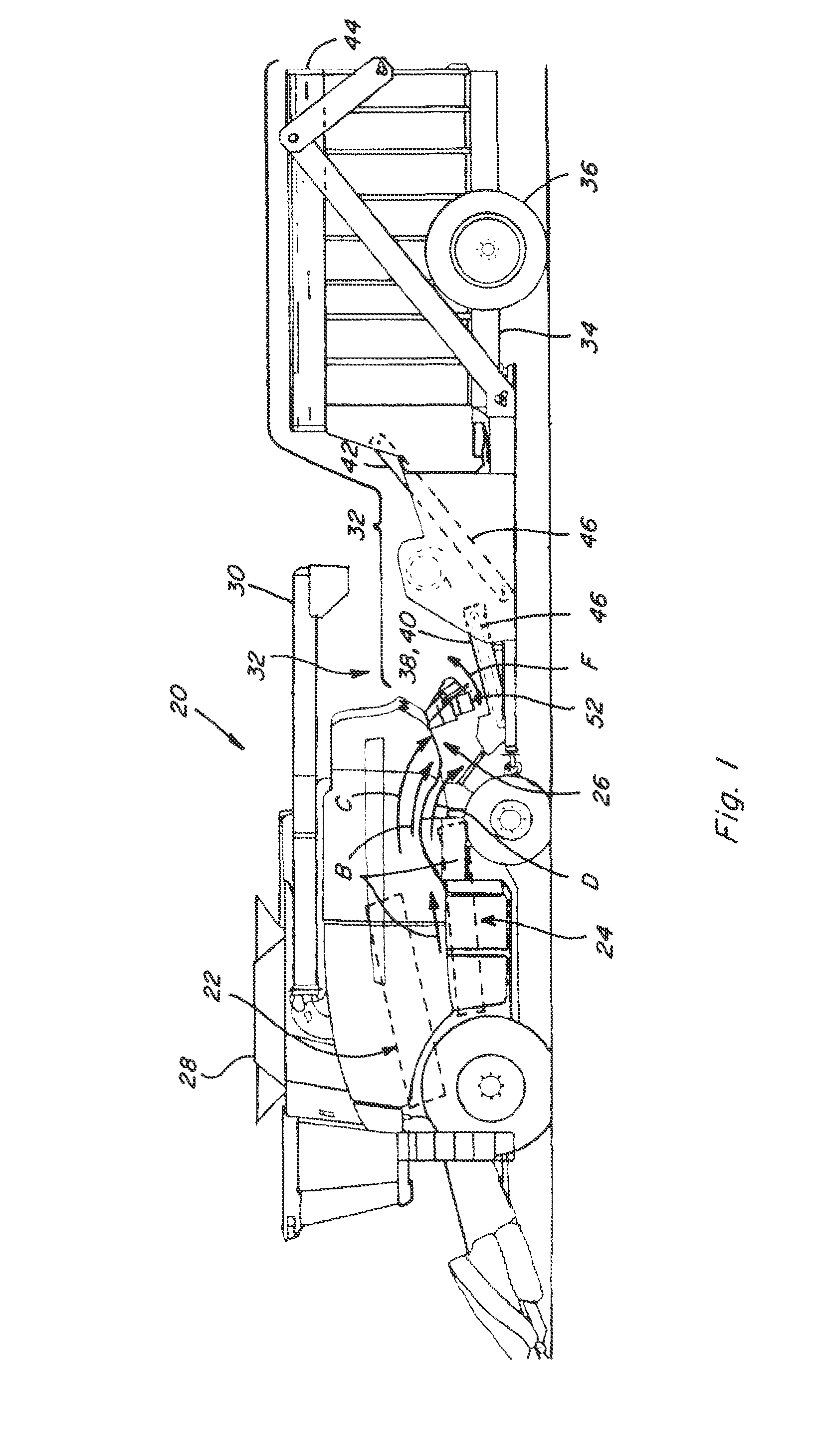
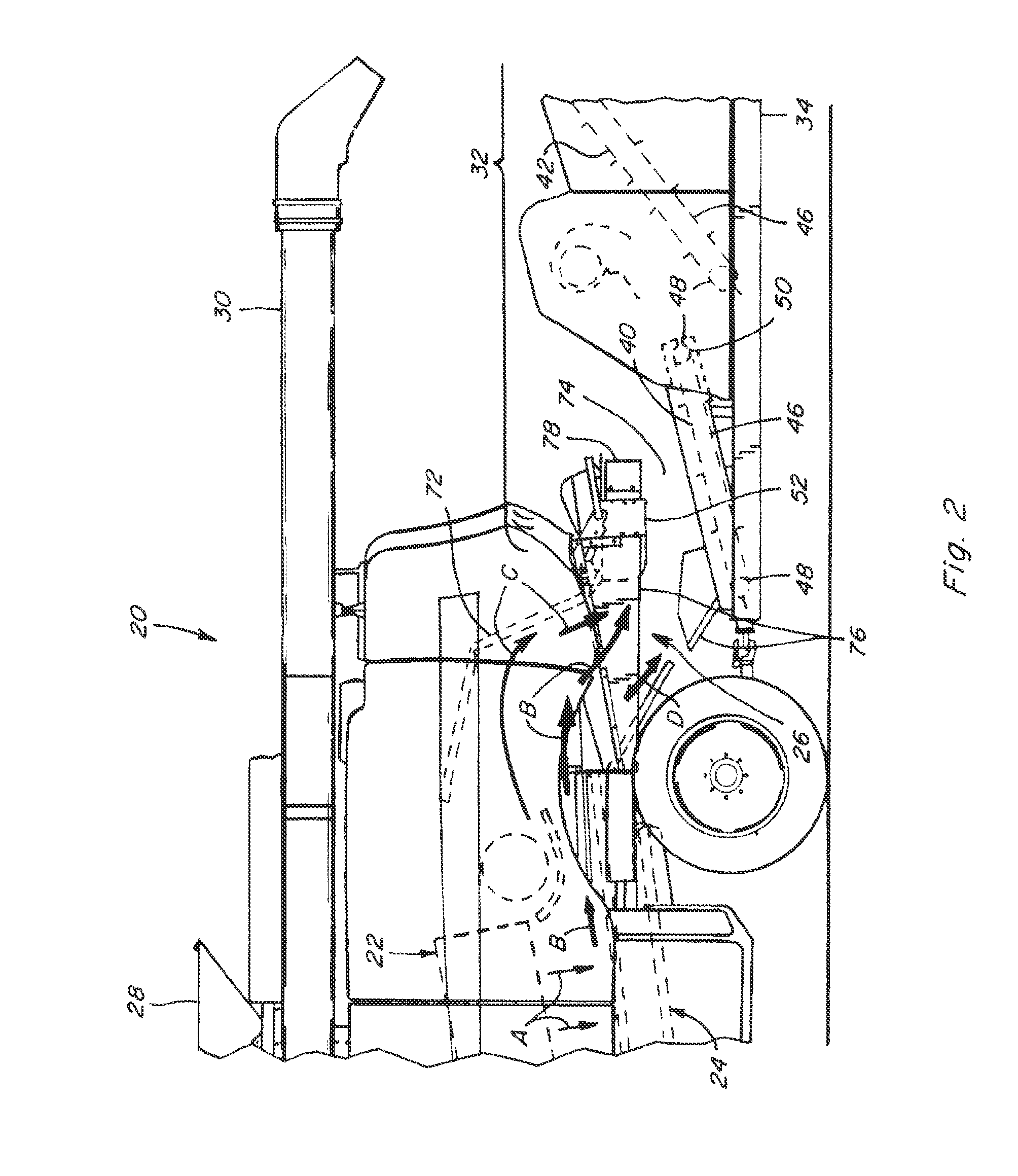
[0030]Referring now the drawings, in FIGS. 1 and 2, a representative agricultural harvesting machine 20 is shown, which is a combine constructed and operable in the well known manner for harvesting whole ears of corn from corn plants as the combine travels over a field. Combine 20 includes well known apparatus that gathers and conveys the ears of corn into a threshing system 22 within the combine which removes most of the husk surrounding the ears, and the corn kernels from cobs of the ears, and directs a flow of the corn, some of the cobs and fragments thereof, and other residue or stover lighter than the corn and cobs, such as fragments of husks, leaves, dust, and the like, all as generally denoted by arrows A, within a rear chamber of combine 20 to a cleaning system 24 of the combine. At the same time, cleaning system 24 has a fan that generates an upward and rearward flow of air, denoted by arrows B, utilized to separate and carry away in an airborne manner the lighter elements ...


PUM


Abstract

A cob conveying and cleaning system for use with a corn harvester, incorporating air induction in cooperation with an air flow from the harvester, for cleaning and separating lighter crop residue to be returned to the field from a mixed flow of the residue and cobs, such that the cleaned cobs can be collected, and the lighter residue optionally spread on the field. The air flow and induction are combined to cooperatively lift or draw the lighter residue from the mixed flow, and to optionally spread the removed lighter residue over a field. The induction apparatus can be located on the harvester, and used as a residue spreader when cobs are not collected.

Description

[0001]This application claims the benefit of U.S. Provisional Application No. 61 / 277,758, filed Sep. 29, 2009.TECHNICAL FIELD[0002]This invention relates generally to a cob conveying system for use with a corn harvester, which more particularly incorporates air induction in cooperation with air flow from the harvester for cleaning and separating lighter crop residue from the cobs, such that the clean cobs can be collected or otherwise utilized, and the inducted lighter residue spread on the field or otherwise disposed of. The invention also relates to residue separation apparatus configurable in multiple modes, including several modes for inductively separating and cleaning lighter crop residue from cobs, and a more traditional crop residue spreading mode.BACKGROUND ART[0003]U.S. Provisional Application No. 61 / 277,758, filed Sep. 29, 2009, is incorporated herein by reference in its entirety.[0004]Presently, there is an increased demand for corn cobs as a feedstock for cellulosic eth...

Claims


Application Information

Patent Timeline
Patent Type & Authority Patents(United States)
IPC IPC(8): A01F12/30
CPCA01D45/02A01D90/02A01F11/06
Inventor RICKETTS, JONATHAN E.BORSDORF, JOHN J.MINNIHAN, JAMES
Owner BLUE LEAF I P INC
Why Eureka
Try Eureka