
Power balanced pipelines

a technology of power balanced pipelines and pipeline stages, applied in the direction of cad circuit design, program control, instruments, etc., can solve the problems of significant imbalance in power consumption of different microarchitecture pipeline stages, significant energy inefficiency in processors, and inefficiency manifesting, so as to reduce power disparity, optimize power efficiency, and maximize frequency

Inactive Publication Date: 2014-08-12
THE BOARD OF TRUSTEES OF THE UNIV OF ILLINOIS
View PDF5 Cites 8 Cited by
  • Summary
  • Abstract
  • Description
  • Claims
  • Application Information

AI Technical Summary

Benefits of technology

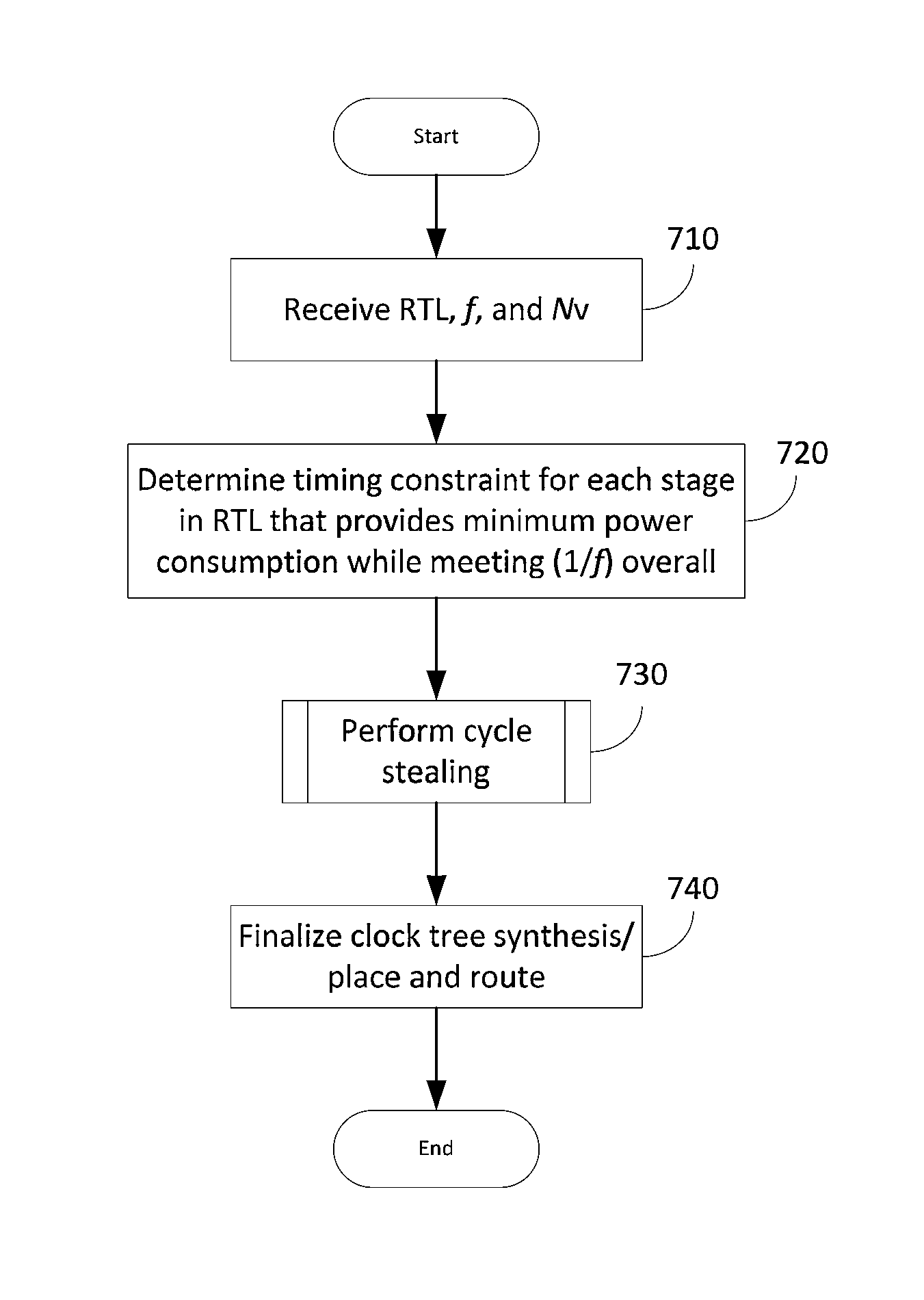
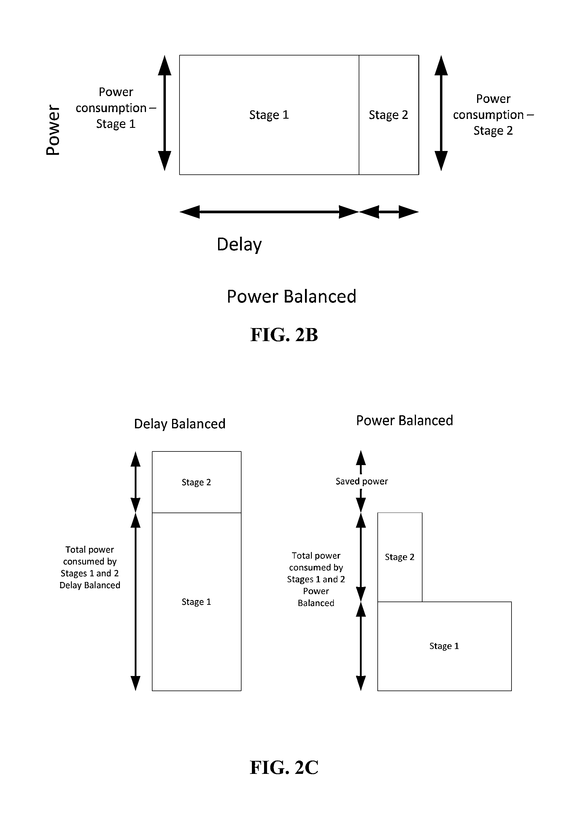
[0007]According to one aspect, different delays are assigned to different microarchitectural pipeline stages to reduce the power disparity between the stages.
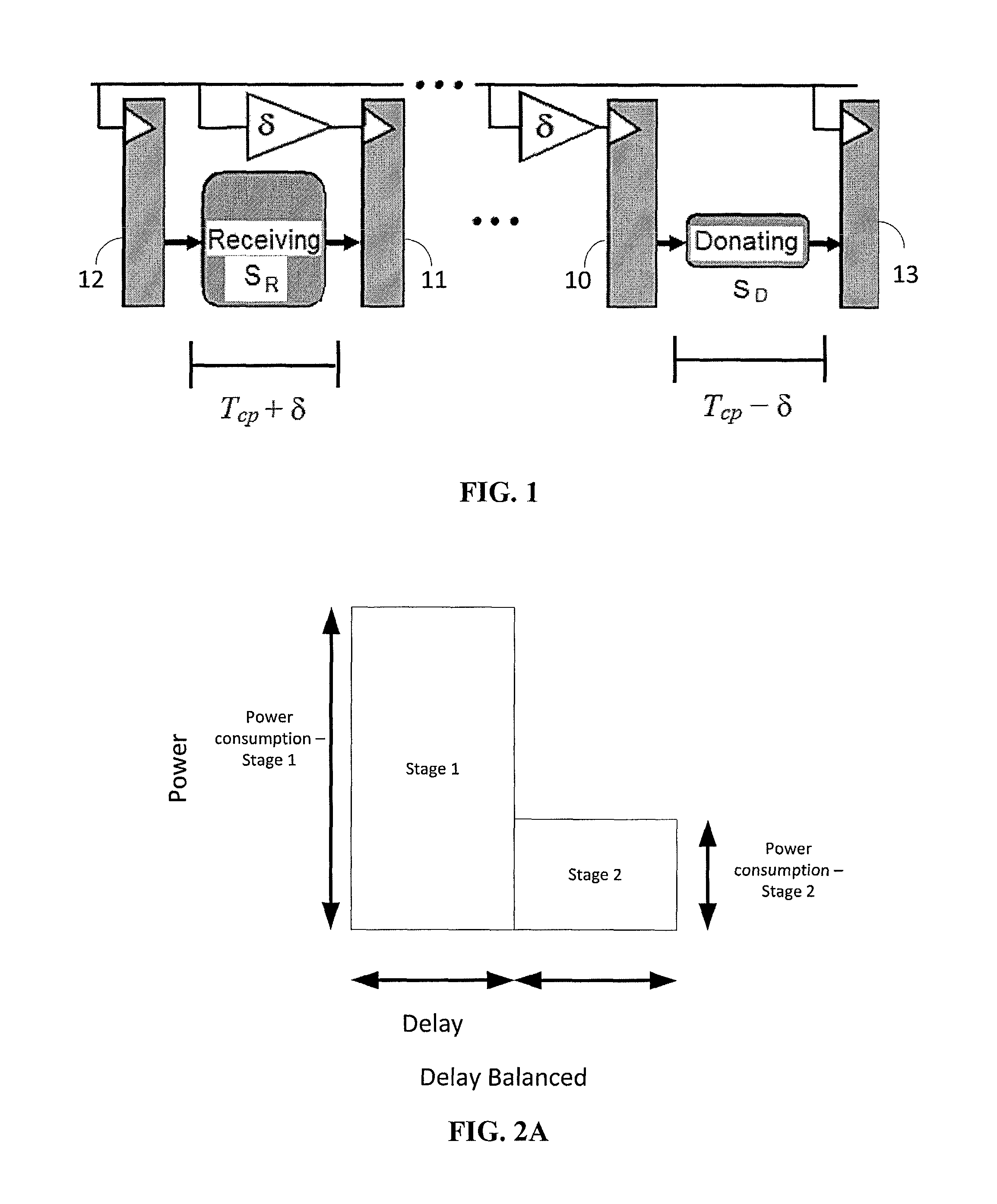
[0008]According to another aspect, power efficiency is optimized through a power balancing technique that utilizes cycle time stealing to maximize frequency by donating time from fast microarchitectural stages to slow microarchitectural stages. Cycle time stealing is used to deliberately redistribute cycle time from low-power pipeline stages to power-hungry stages, relaxing their timing constraints and allowing them to operate at reduced voltages or use smaller, less leaky cells.
[0011]Another static technique can be applied during test phase of a processor chip. In one embodiment, a voltage assignment technique that balances power at test time is provided that can improve power efficiency of a processor with or without design-level optimizations.

Problems solved by technology

Although balancing delay across pipeline stages increases instruction throughput, a delay-balanced approach can cause significant energy inefficiency in processors because each microarchitectural pipeline stage gets the same amount of time to complete, irrespective of its size or complexity.
For power-optimized processors (i.e., processors where circuit and design-level optimizations reclaim timing slack to save power), the inefficiency manifests itself as a significant imbalance in power consumption of different microarchitectural pipeline stages.

Method used


Image

  • Power balanced pipelines
  • Power balanced pipelines
  • Power balanced pipelines

Examples


examples

Example: Experimental Setup and Simulations

[0139]The FabScalar framework is used to evaluate power balanced pipelines of embodiments of the invention. FabScalar is a parameterizable, synthesizable processor specification that allows for the generation and simulation of RTL descriptions for arbitrarily configured scalar and superscalar processor architectures. For the evaluations, benchmarks from the Standard Performance Evaluation Corporation (SPEC) benchmark suite (INT, bzip, crafty, gap, mcf, parser, twolf, vortex, FP, ammp, art, equake, swim, wupwise) are executed for 3 billion cycles.

[0140]FIG. 13 shows the average power breakdown (for a workload of SPEC benchmarks) into the stages of the baseline FabScalar pipeline used in the experiment examples. Canonical pipeline states include Fetch, Decode, Rename & Retire, Dispatch, Issue, Register read (RegRead), Execute, and WriteBack / Bypass.

[0141]Floating Point (FP) benchmarks are primarily used to evaluate dynamic power balancing sinc...


PUM


Abstract

Power balancing techniques are provided for improving power efficiency of pipelined processors. A design-level implementation can be incorporated during synthesis of pipeline clocks in which a register transfer level (RTL) code, operating frequency, and available voltage domains are used to perform cycle time stealing with, and optimize for, power efficiency. A test-level implementation can be incorporated during testing of a chip in which delay and power measurements are used to perform calculations based on cycle time stealing and optimization of power efficiency. The calculations are then used to perform voltage scaling and / or adjust tunable delay buffers. Process variations may also be corrected during test time. A run-time approach can be incorporated for dynamic power balancing in which the operating system keeps track of one or more performance indicators such as a count of floating point instructions and uses a look-up table to provide the appropriate delays.

Description

BACKGROUND[0001]Current processor architecture design involves “pipelining” in which instructions are broken into smaller steps referred to as “stages” and performed in a manner reminiscent of an assembly line. Generally, each stage is assigned a certain amount of time to be performed. This is also referred to as “delay”. Pipelined processors are popular because once all the stages of the pipeline are filled (i.e. executing their assigned step), it only takes a length of one cycle (the delay of a stage) to complete an instruction. In this manner, the computer's cycle time is the time of the slowest stage in the pipeline.[0002]It is generally understood that the throughput of a processor pipeline is maximized when the total latency of the pipeline is divided evenly between all the stages. Thus, balancing the delay of the microarchitectural pipeline stages such that each microarchitectural pipeline stage has an equal delay has been a primary design objective in order to maximize instr...

Claims


Application Information

Patent Timeline
Patent Type & Authority Patents(United States)
IPC IPC(8): G06F17/50
CPCG06F17/505G06F2217/84G06F17/5022G06F2217/14G06F2217/78G06F30/333G06F30/327G06F2119/12G06F30/33G06F2119/06G06F2115/10G06F30/396G06F30/3308
Inventor KUMAR, RAKESHAHRENS, BENJAMIN J.SARTORI, JOHN M.
Owner THE BOARD OF TRUSTEES OF THE UNIV OF ILLINOIS
Learn More