
Vehicle braking system and master cylinder

a brake system and master cylinder technology, applied in brake systems, rotary clutches, fluid couplings, etc., can solve problems such as difficulty in obtaining a good pedal feel over a larger range, and achieve good pedal feel

Active Publication Date: 2014-08-19
HITACHI ASTEMO LTD
View PDF10 Cites 3 Cited by
  • Summary
  • Abstract
  • Description
  • Claims
  • Application Information

AI Technical Summary

Benefits of technology

This configuration enhances the braking system's ability to maintain a good pedal feel and sufficient braking force by adjusting hydraulic pressure dynamically, ensuring deceleration rates and pedal stroke optimization across various operating conditions.

Problems solved by technology

Accordingly, it is difficult to obtain a good pedal feel over a larger range.

Method used


Image

  • Vehicle braking system and master cylinder
  • Vehicle braking system and master cylinder
  • Vehicle braking system and master cylinder

Examples


first embodiment

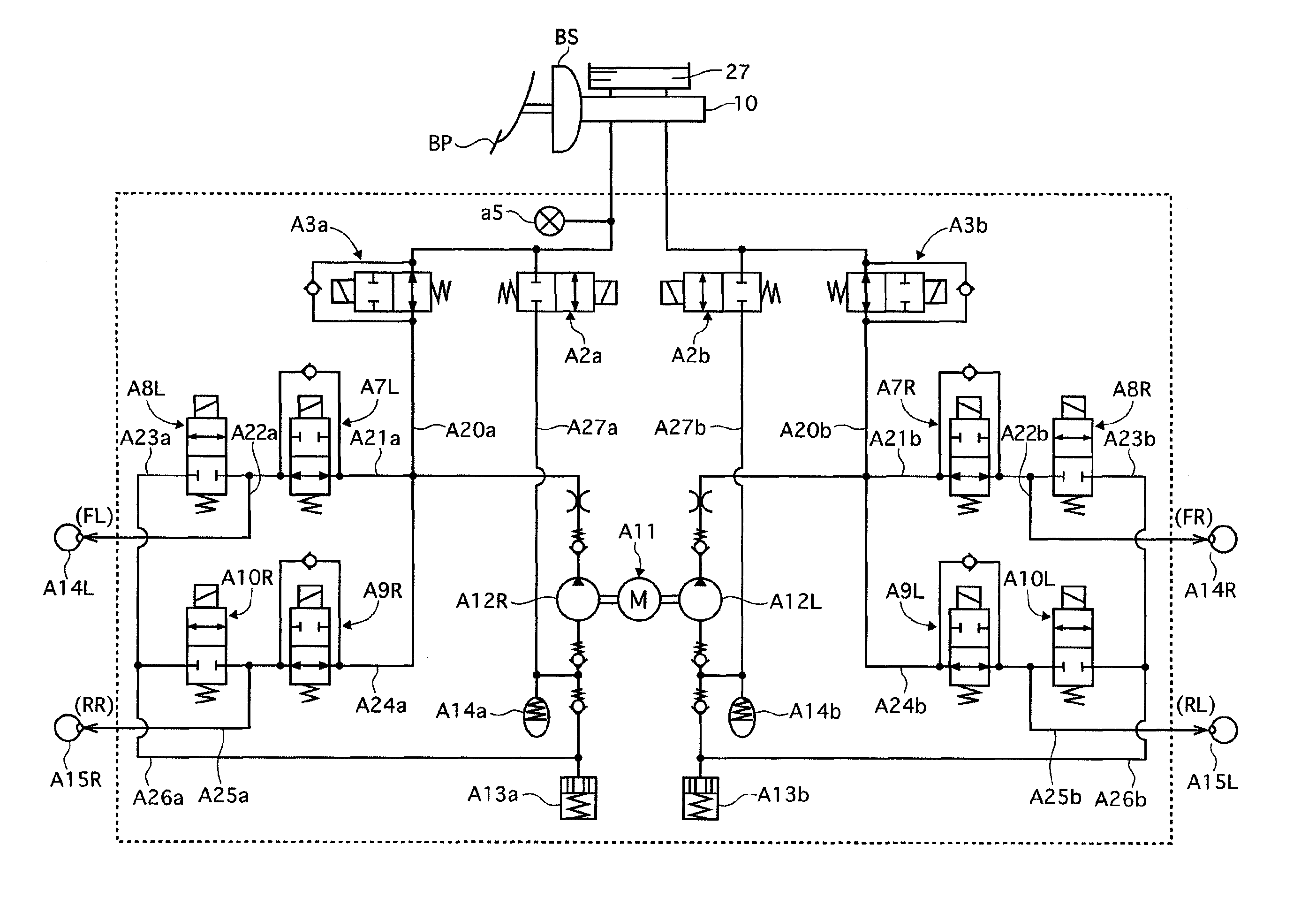
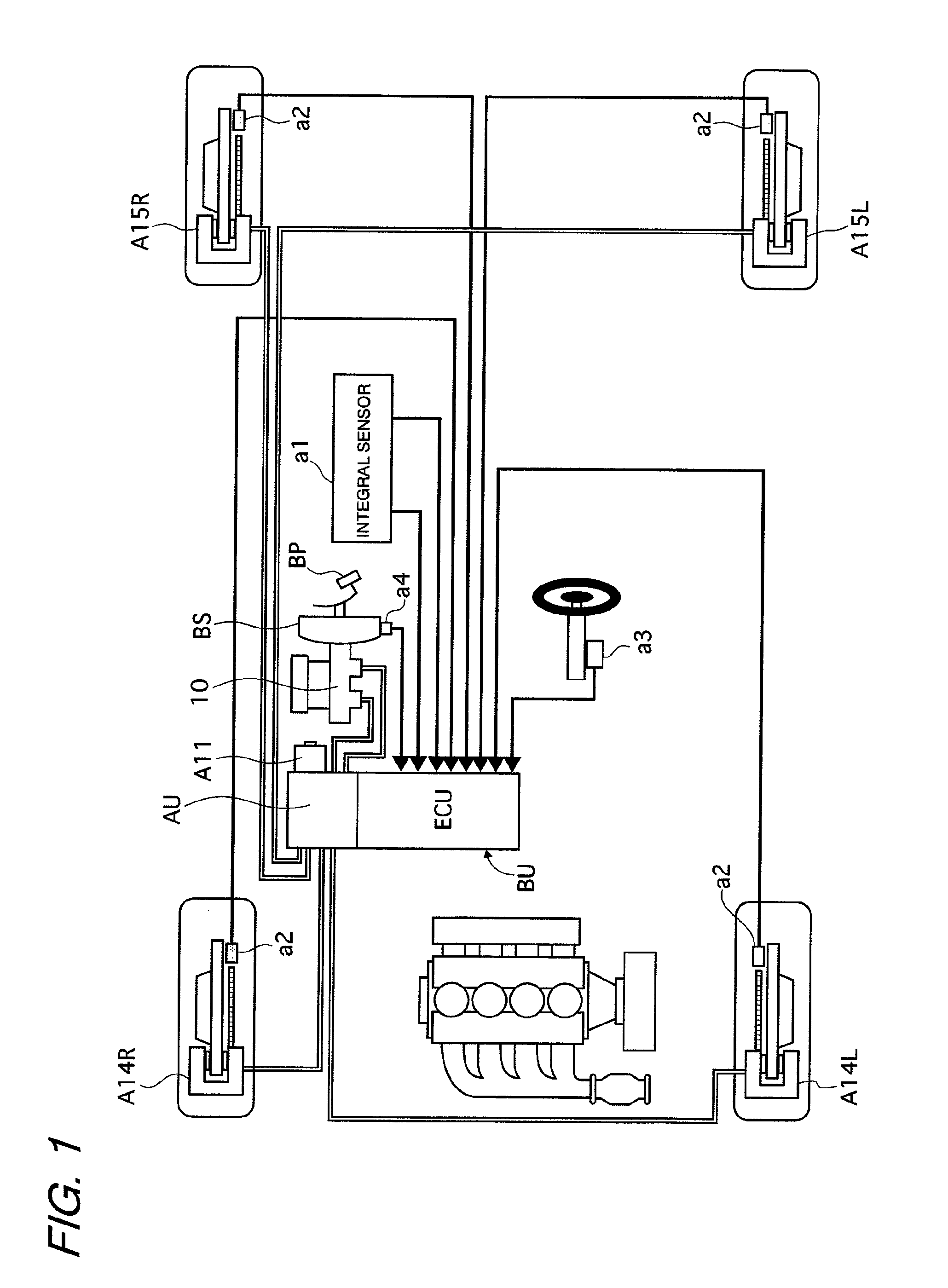
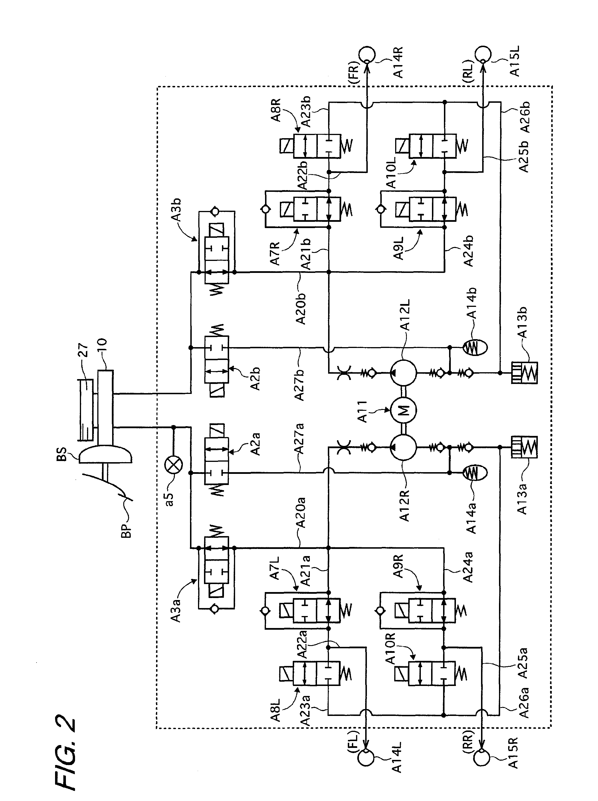
[0018]First, a configuration of a first embodiment is described referring to FIG. 1. A brake control unit BU according to the first embodiment includes: an integral sensor a1 which detects a yaw rate, a lateral acceleration, and a longitudinal acceleration of a vehicle; wheel-speed sensors a2; a steering-angle sensor a3 which detects a steering angle of a steering wheel steered by a driver; a negative-pressure sensor a4 which detects a negative pressure of a booster BS; and a hydraulic-pressure sensor a5 which detects a hydraulic pressure generated in a pressure chamber (small-diameter pressure chamber 61) of a master cylinder 10 (FIG. 2). The hydraulic pressure output from the brake control unit BU is supplied to wheel cylinders A14 (A14L, A14R) and A15 (A15L, A15R) of the respective wheels to achieve a desired braking force.

[0019]A pressing force input to a brake pedal BP operated by the driver is assisted by the booster BS, and the thus assisted piston-pushing force is transmitte...

second embodiment

[0158]In the first embodiment described above, the hydraulic pressure corresponding to 2.5 m / s2 is set to 2.3 MPa, and the hydraulic pressure at which the control valve 75 functioning as the pressure-reducing valve is opened is set as high as about 4 MPa. However, the valve-opening pressure for the control valve 75 is not limited thereto. The hydraulic pressure corresponding to 2.5 m / s2 may be set to a lower value within the aforementioned hydraulic-pressure range of 1.7 MPa to 2.9 MPa, for example, to 1.7 MPa so that the hydraulic pressure at which the control valve 75 is opened may be set to 2 MPa.

[0159]In the case of the setting as described above, the relation between the pressing force (muscle force) and the master cylinder hydraulic pressure is as shown in FIG. 10. When the booster BS operates normally, the assist force is generated by the booster BS as a result of the generation of the pressing force on the brake pedal by the driver. Then, the driver can obtain the master cyl...


PUM


Abstract

Provided are a vehicle braking system and a master cylinder which are capable of providing a good pedal feel. A valve-opening pressure for a pressure-reducing valve of the master cylinder is set higher than a hydraulic pressure which is obtained with a pressing force on a brake pedal being 500 N and lower than a hydraulic pressure obtained at a time when a booster reaches a full-load point in case of failure of the booster so as to be specialized for improving pedal feel. Required performance in case of failure of the booster is realized by a pressure-intensifying unit.

Description

BACKGROUND OF THE INVENTION[0001]The present invention relates to a vehicle braking system and a master cylinder.[0002]As a technology for shortening a stroke of a brake pedal so as to obtain a good pedal feel, a master cylinder including a large-diameter pressurized chamber and a small-diameter pressure chamber is known, for example. The master cylinder performs so-called fast fill for supplying a large volume of brake fluid from the large-diameter pressurized chamber to the small-diameter pressure chamber during an initial stage of the stroke so as to compensate for an ineffective fluid amount during the initial stage of the stroke. Thereafter, a pressure-reducing valve is opened at a predetermined hydraulic pressure to reduce a hydraulic pressure in the large-diameter pressurized chamber. As a result, a desired braking force is obtained while the stroke of the brake pedal during the initial stage of the stroke is shortened. An example of the master cylinder as described above is ...

Claims


Application Information

Patent Timeline
Patent Type & Authority Patents(United States)
IPC IPC(8): B60T8/88B60T7/04B60T8/42B60T11/18
CPCB60T11/18B60T7/042Y10S303/02
Inventor KOSHIMIZU, NAGANORIOGIWARA, TAKATO
Owner HITACHI ASTEMO LTD
Learn More