Container filling device

a container and drive device technology, applied in the direction of metal sawing devices, liquid handling, manufacturing tools, etc., can solve the problem of not providing the coupling of the support elements through a common endless drive devi

Active Publication Date: 2014-08-26
HAMBA FILLTEC
View PDF6 Cites 2 Cited by
  • Summary
  • Abstract
  • Description
  • Claims
  • Application Information

AI Technical Summary

Benefits of technology

[0011]An elevator of this type significantly simplifies so-called format change, thus changing the support elements for filling other container types and sizes may be easily performed since the movement paths of the support elements in the main elements are freely accessible. Thus, the support elements can be retrieved or removed in a simple manner without being impeded by the elevator components and / or mechanisms at an end of the respective main element or they can be joined in a simple manner at the beginning of the respective main element. According to the invention, the lateral elements with their elevators do not impede retrieving the support elements at the lateral element.
[0013]In this embodiment, no retaining elements, that need to be produced separately and which have to receive the support elements, have to be used. Instead, the support element is moved out of the main element to continue its movement path without having to be joined to a separate device.
[0014]In order to provide a clean axial orientation of the support elements with respect to a longitudinal axis of the device on a path of the support elements between the main elements and for respective rejoining and in order to assure that the support element can be moved with precise positioning between the main elements, the elevator may include a guide device which provides a precisely positioned arrangement of a support element in the elevator during the vertical movement.
[0021]This facilitates that the support element is moved through the lifting device from below relative to the placement surface of the device to the operating element of the drive.

Problems solved by technology

Coupling of the support elements through a common endless drive device, however, is not provided.

Method used


Image

  • Container filling device
  • Container filling device
  • Container filling device

Examples


Embodiment Construction

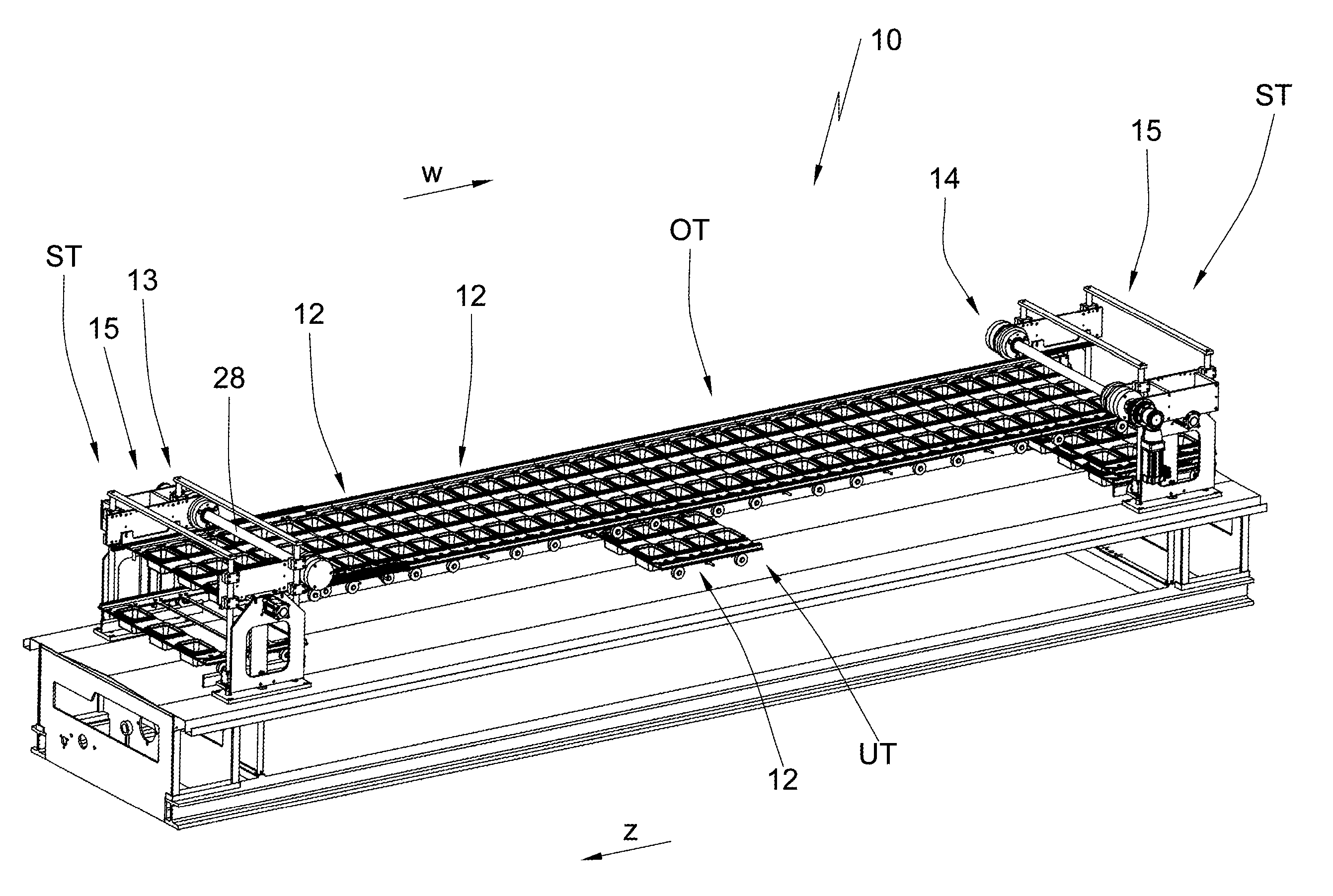
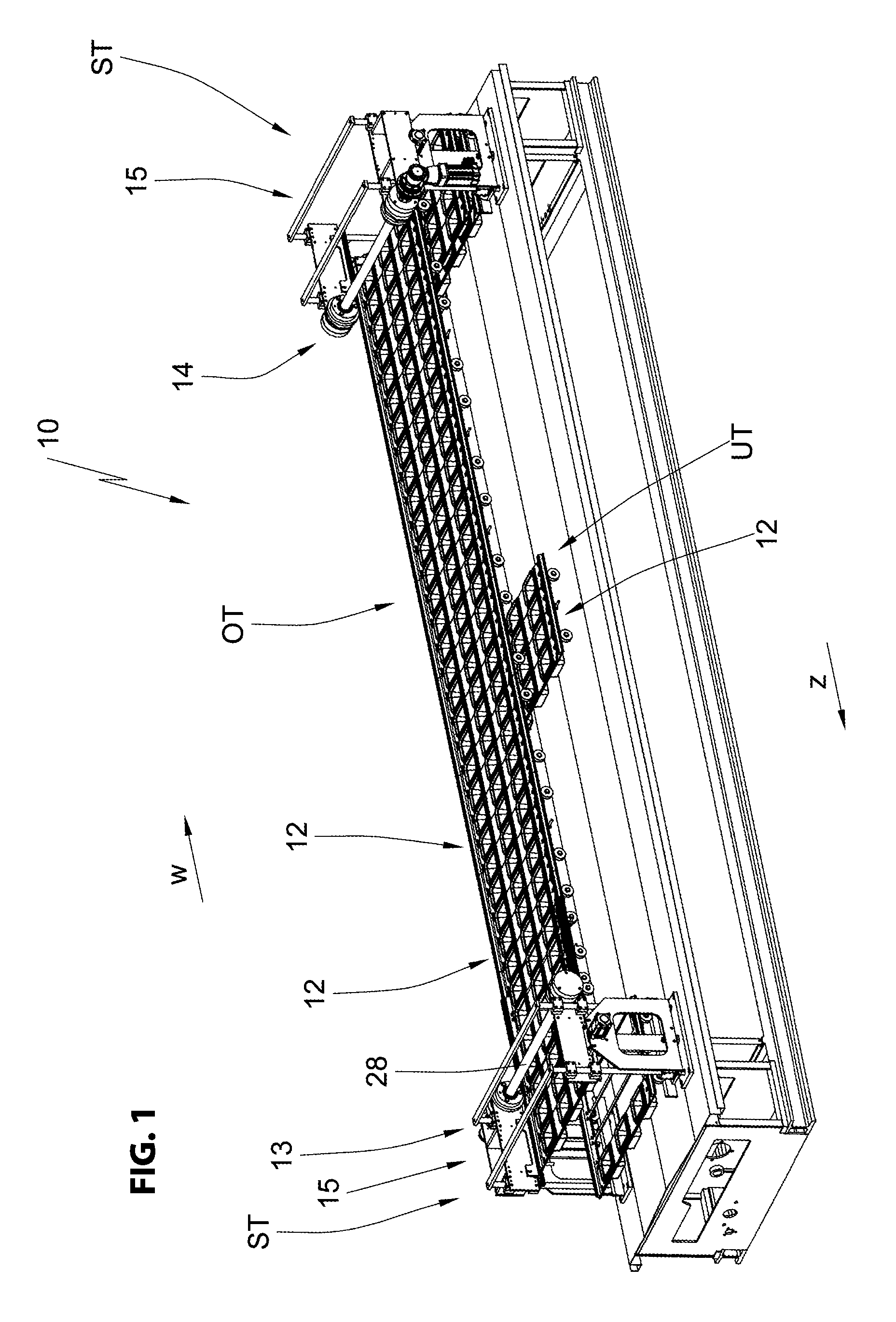
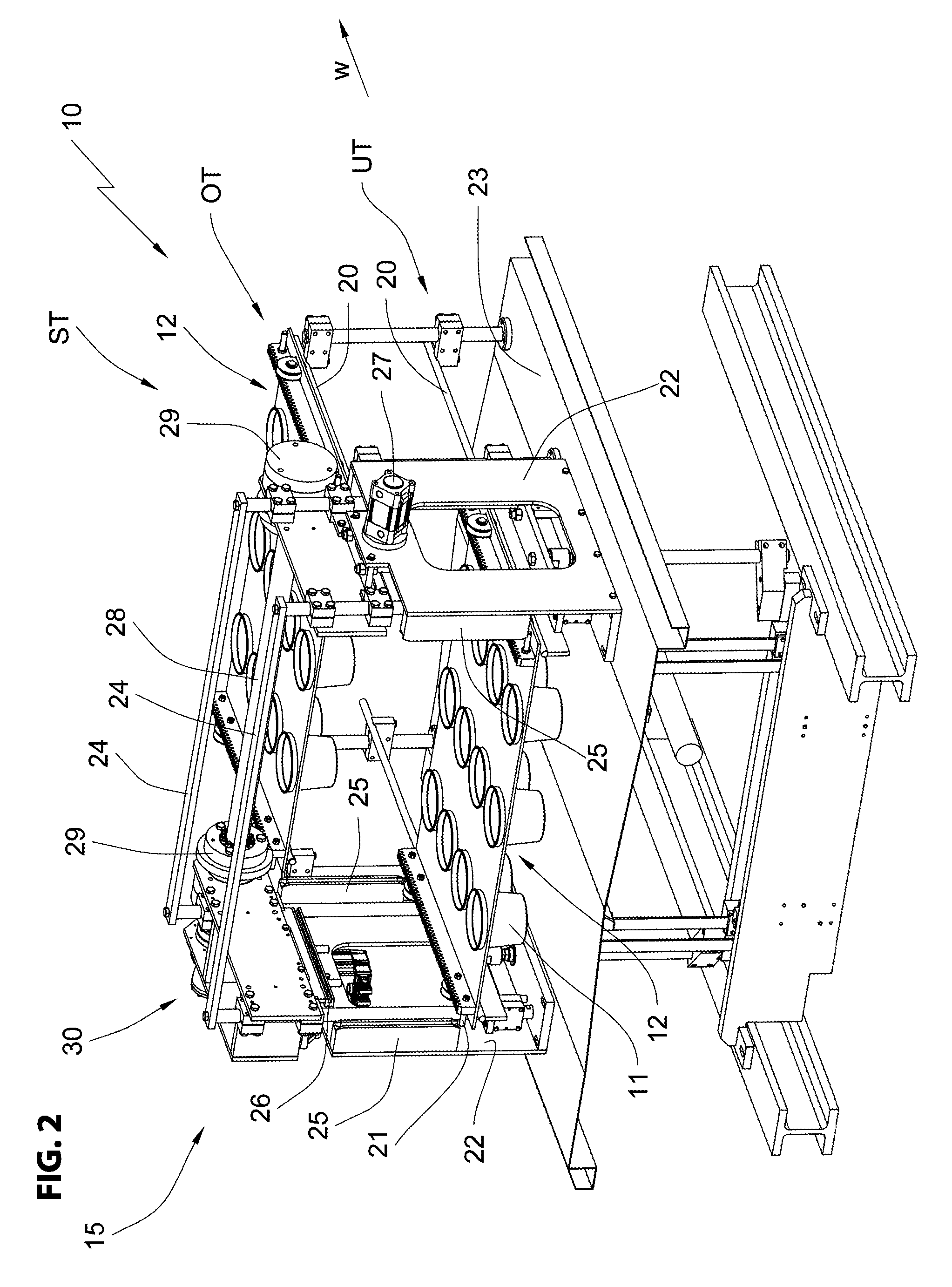
[0029]A device according to the invention is designated in the figures with the overall reference numeral 10.

[0030]The device 10 is used for filling liquid to pasty food products into containers 11 which are run through the device 10 on support elements which are overall designated with the reference numeral 12 along operating stations that are not illustrated.

[0031]The device 10 comprises an upper main element OT oriented horizontally with respect to the placement surface of the device 10 and a lower main element UT arranged parallel to the upper main element. Typically, operating stations for treating the containers 11 are arranged above the upper main element OT, however there are also systems where the operating stations are arranged between the upper main element OT and lower main element UT and the containers 11 are treated in the lower main element UT. Therefore, the upper main element OT and the lower main element UT can both be described as main elements.

[0032]In order to p...


PUM

PropertyMeasurementUnit
vertical movementaaaaaaaaaa
movementaaaaaaaaaa
mechanical configurationaaaaaaaaaa

Abstract

A device for filling containers, in particular bottles or beakers with food products, comprising: an upper main element, a lower main element which are the main elements of the device; lateral elements connecting the main elements; a plurality of support elements continuously arranged at one another without a continuous drive device and provided with receivers for the containers and moved through the device and along the elements and along operating stations; running rails on which the support elements rest while being moved through the main elements; a drive which moves the support elements at least along the operating stations; and at least one lateral element configured as an elevator through which the support elements alternate between the main elements when moving through the device, wherein the elevator includes a exclusively vertically movable lifting device for moving the support elements from one main element into another main element.

Description

RELATED APPLICATIONS[0001]This application claims priority from and incorporates by reference German patent application DE 10 2011 103 256.1 filed on May 25, 2011FIELD OF THE INVENTION[0002]The present invention relates to a device for filling containers, in particular bottles or beakers with food products, in particular liquid to paste-like dairy- and fat products, juices, waters and similar products. In an embodiment, the device includes an upper main element, a lower main element, lateral elements connecting the upper and lower main elements together, and a plurality of support elements arranged with one another without a continuous drive device. The support elements comprise receivers for the containers and may be moved through the filling device. The support elements may be moved along the main elements and through operating stations while resting on and supported by running rails on the upper main element and the lower main element. The device further comprises a drive which m...

Claims


Application Information

Patent Timeline
Patent Type & Authority Patents(United States)
IPC IPC(8): B65G33/04B65B9/04B65B43/52B65B43/54B65B65/02B65G35/08B67C3/24
CPCB67C3/24B65B65/02B65G35/08B65B43/52B65B43/54B65B9/042
Inventor JUNK, MARTIN
Owner HAMBA FILLTEC
Why Eureka
Try Eureka