
System and method for protection during inverter shutdown in distributed power installations

a distributed power system and inverter technology, applied in transmission systems, dc source parallel operation, sustainable buildings, etc., can solve problems such as shock or electrocution of repairmen, photovoltaic installation, and islanding, and complicate the orderly reconnection of the utility network

Active Publication Date: 2014-08-26
SOLAREDGE TECH LTD
View PDF498 Cites 162 Cited by
  • Summary
  • Abstract
  • Description
  • Claims
  • Application Information

AI Technical Summary

Benefits of technology

The solution effectively prevents islanding conditions, ensuring safety for personnel and equipment by promptly disconnecting from the grid and reducing waveform distortion, while allowing for efficient power harvesting and compliance with safety regulations.

Problems solved by technology

One common problem faced by modern utility networks is the occurrence of islanding.
Otherwise the photovoltaic installation may shock or electrocute repairmen after the grid is shut down from the photovoltaic installation generating power as an island downstream.
The island condition complicates the orderly reconnection of the utility network and poses a hazard also to equipment.
The drawback of such a method is that often the point of utility isolation (the point at which the utility circuit breaker opens) is of such a distance from the local distributed power system that running a contact status signal back to the local distributed power system control system is not practical.
With active schemes, some distortion may occur in the output current waveform, thereby resulting in a tradeoff between islanding detection time and waveform distortion, with faster detection typically resulting in higher total harmonic distortion.
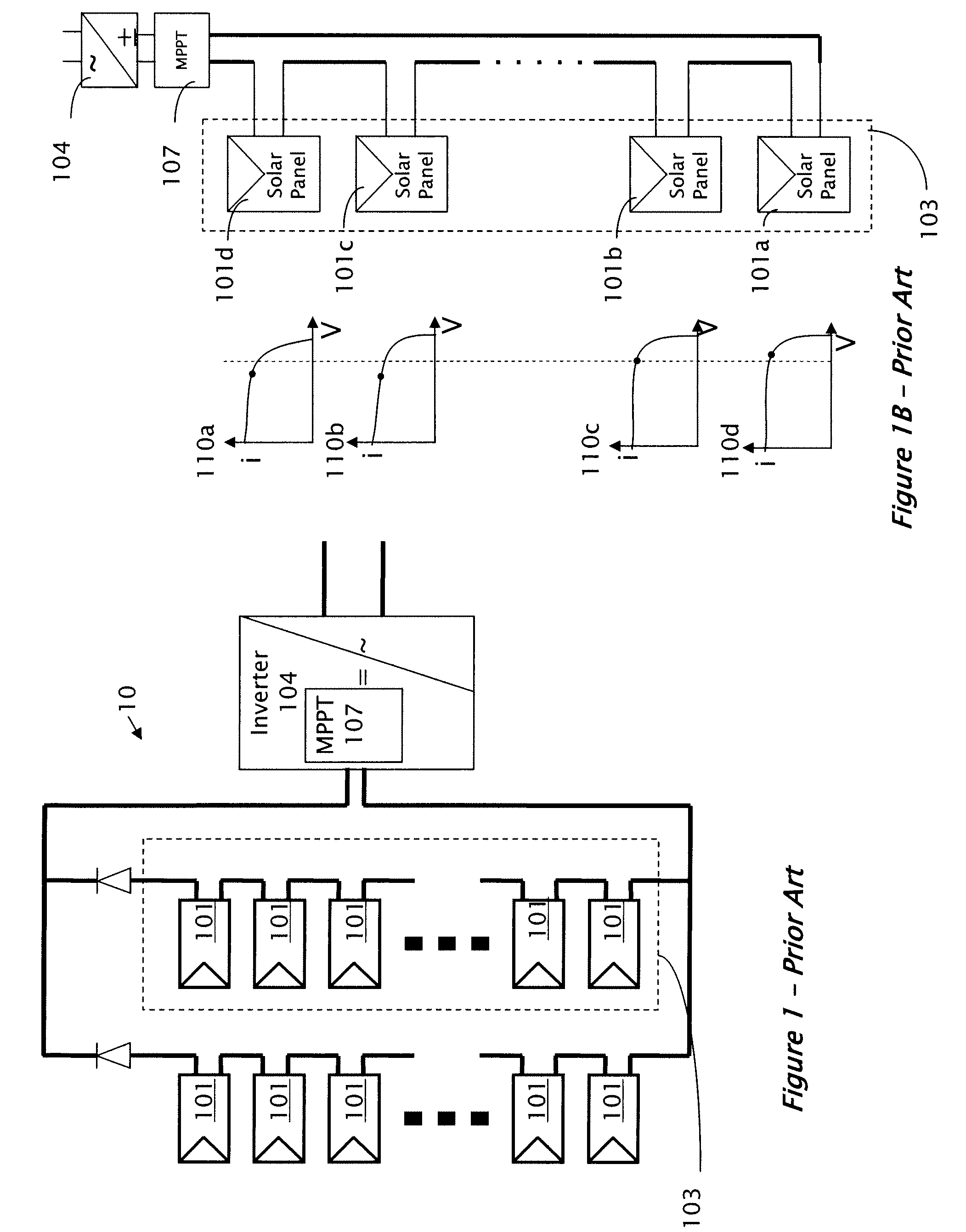
A problem facing the solar array designer is to produce a standard AC current at 120V or 220V root-mean-square (RMS) from a combination of the low voltages of the solar panels.
The delivery of high power from a low voltage requires very high currents, which cause large conduction losses on the order of the second power of the current i2.
Consequently, the arrangement is not operated at best achievable efficiency.

Method used


Image

  • System and method for protection during inverter shutdown in distributed power installations
  • System and method for protection during inverter shutdown in distributed power installations
  • System and method for protection during inverter shutdown in distributed power installations

Examples


Embodiment Construction

[0032]Reference will now be made in detail to embodiments of the present invention, examples of which are illustrated in the accompanying drawings, wherein like reference numerals refer to the like elements throughout. The embodiments are described below to explain the present invention by referring to the figures.

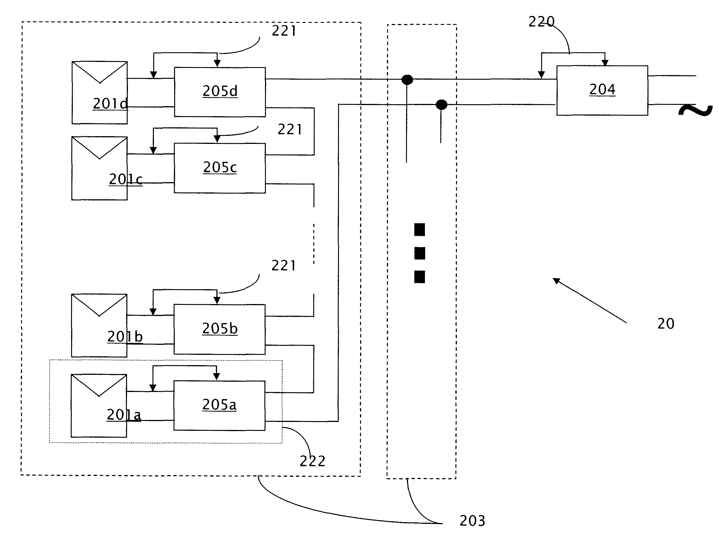
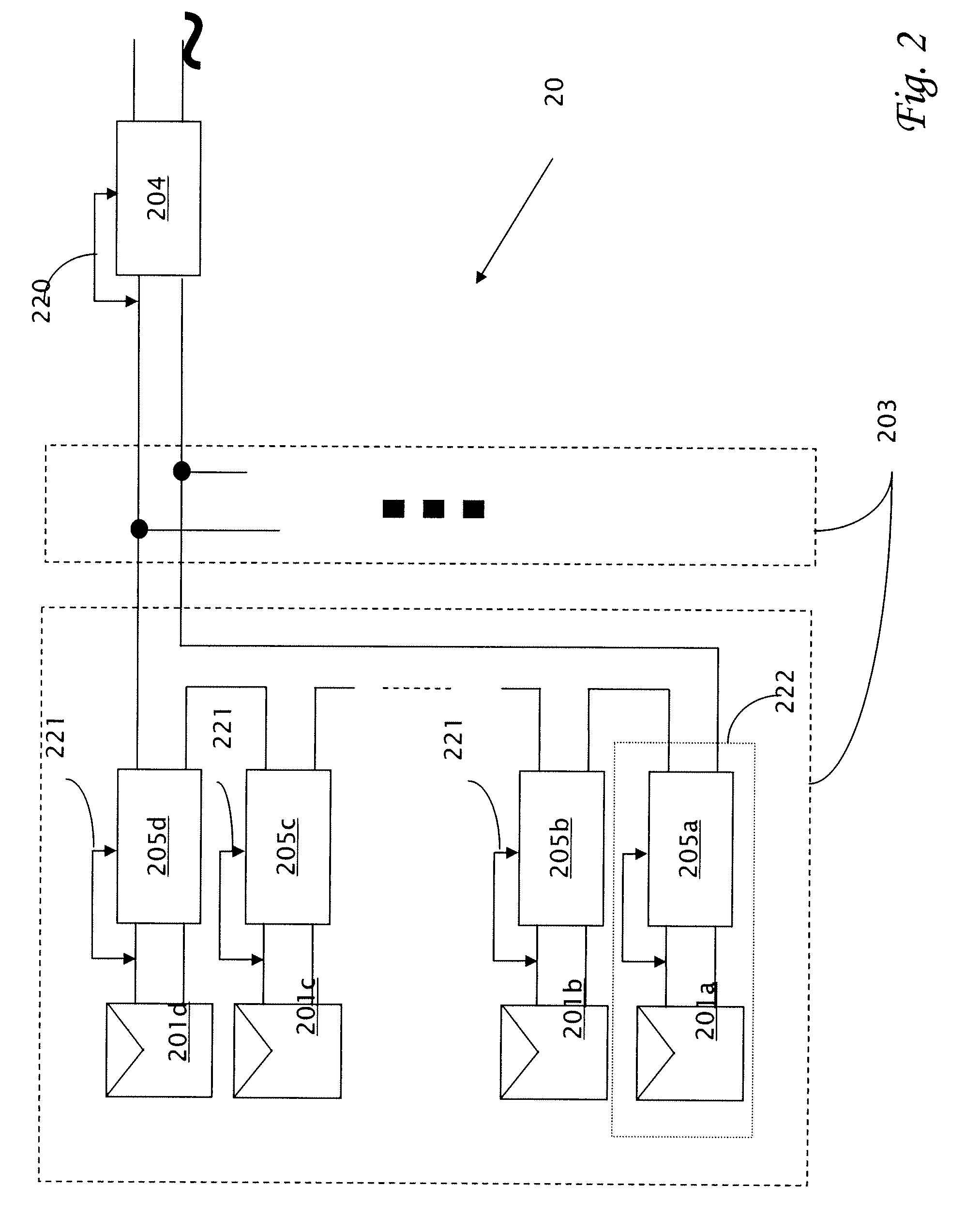
[0033]It should be noted, that although the discussion herein relates primarily to anti-islanding in photovoltaic systems and more particularly to those systems previously disclosed in U.S. application Ser. No. 11 / 950,271, the present invention may, by non-limiting example, alternatively be configured as well using conventional photovoltaic distributed power systems and other distributed power systems including (but not limited to) wind turbines, hydroturbines, fuel cells, storage systems such as battery, super-conducting flywheel, and capacitors, and mechanical devices including conventional and variable speed diesel engines, Stirling engines, gas turbines, and micro-turb...


PUM


Abstract

A protection method in a distributed power system including of DC power sources and multiple power modules which include inputs coupled to the DC power sources. The power modules include outputs coupled in series with one or more other power modules to form a serial string. An inverter is coupled to the serial string. The inverter converts power input from the string and produces output power. When the inverter stops production of the output power, each of the power modules is shut down and thereby the power input to the inverter is ceased.

Description

CROSS REFERENCE TO RELATED APPLICATIONS[0001]The present application is a continuation-in-part of co-pending U.S. application Ser. No. 11 / 950,271 filed Dec. 4, 2007 by the present inventors, the disclosure of which is included herein by reference for all purposes as if entirely set forth herein.[0002]The present application claims priority benefits from U.S. provisional application 60 / 978,764 filed Oct. 10, 2007 by the present inventors, the entire disclosure of which is incorporated herein by reference.FIELD AND BACKGROUND[0003]The present invention relates to anti-islanding in a distributed power system and, more particularly, system and method for protection of photovoltaic distributed power equipment and personnel during anti-islanding.[0004]Utility networks provide an electrical power system to utility customers. The distribution of electric power from utility companies to customers utilizes a network of utility lines connected in a grid-like fashion, referred to as an electric...

Claims


Application Information

Patent Timeline
Patent Type & Authority Patents(United States)
IPC IPC(8): H02J1/10H02J3/38
CPCH02J3/38H02J1/10H02M1/36H02J3/386Y10T307/50Y02E10/566Y10T307/729H02J7/35H02J3/383Y02E10/563Y10T307/724Y10T307/707H02H7/1227Y02E10/763Y10T307/735H02J1/102H04B3/548H02J2300/10H02J2300/28H02J2300/24H02J3/381Y02B10/30Y02B10/10Y02E10/56Y02E10/76H02J3/388H02H7/1213H02H3/087
Inventor ADEST, MEIRSELLA, GUYHANDELSMAN, LIORGALIN, YOAVFISHELOV, AMIRGAZIT, MEIR
Owner SOLAREDGE TECH LTD
Learn More