

Switching power supply
a power supply and switching technology, applied in the field of switching power supplies, can solve the problems of increasing the size of the casing b>92/b>, the number of steps of the switching power supply b>90/b> of the conventional art, and the need for a number of parts, so as to reduce the number of steps and reduce the number of parts.
- Summary
- Abstract
- Description
- Claims
- Application Information
AI Technical Summary
Benefits of technology
Problems solved by technology
Method used
Image

Examples
first embodiment
(First Embodiment)
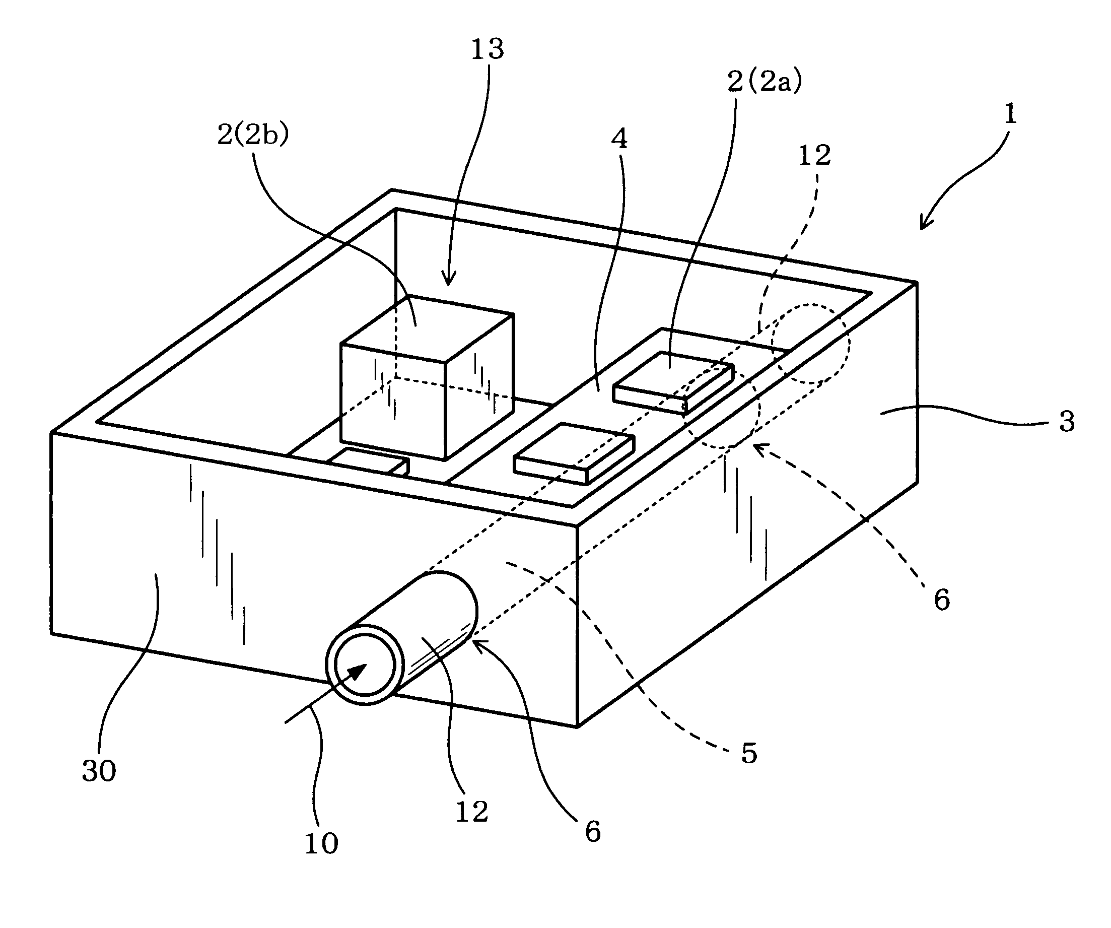
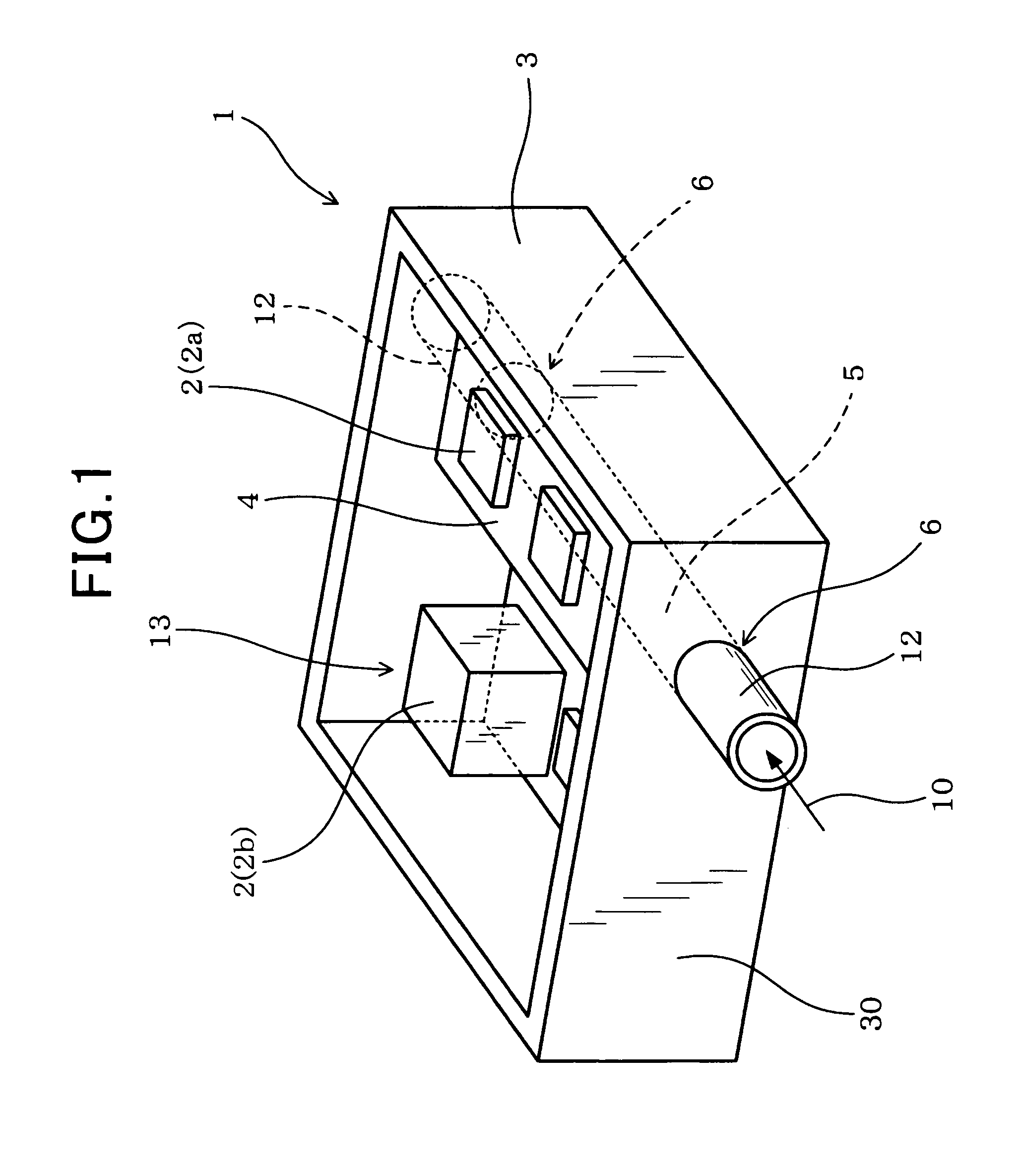
[0061]Referring to FIGS. 1 to 5, hereinafter is described a switching power supply according to a first embodiment of the present disclosure. FIG. 1 is a perspective view illustrating a switching power supply 1 according to the first embodiment.
[0062]As shown in FIG. 1, the switching power supply 1 of the present embodiment includes a switching circuit 13, electronic parts 2 configuring the switching circuit 13, a seat member 4 on which the electronic parts 2 are mounted and a coolant channel 5 through which a coolant 10 flows.
[0063]The electronic parts 2 are accommodated in a casing 3. The seat member 4 is integrally formed with the casing 3. The coolant channel 5 is formed through the seat member 4 so as to be open at least at two positions of an outer wall surface 30 of the casing 3.
[0064]The coolant 10 that flows through the coolant channel 5 cools the electronic parts 2 mounted on the seat member 4.
[0065]Specific description is set forth below.
[0066]As shown i...
second embodiment
(Second Embodiment)
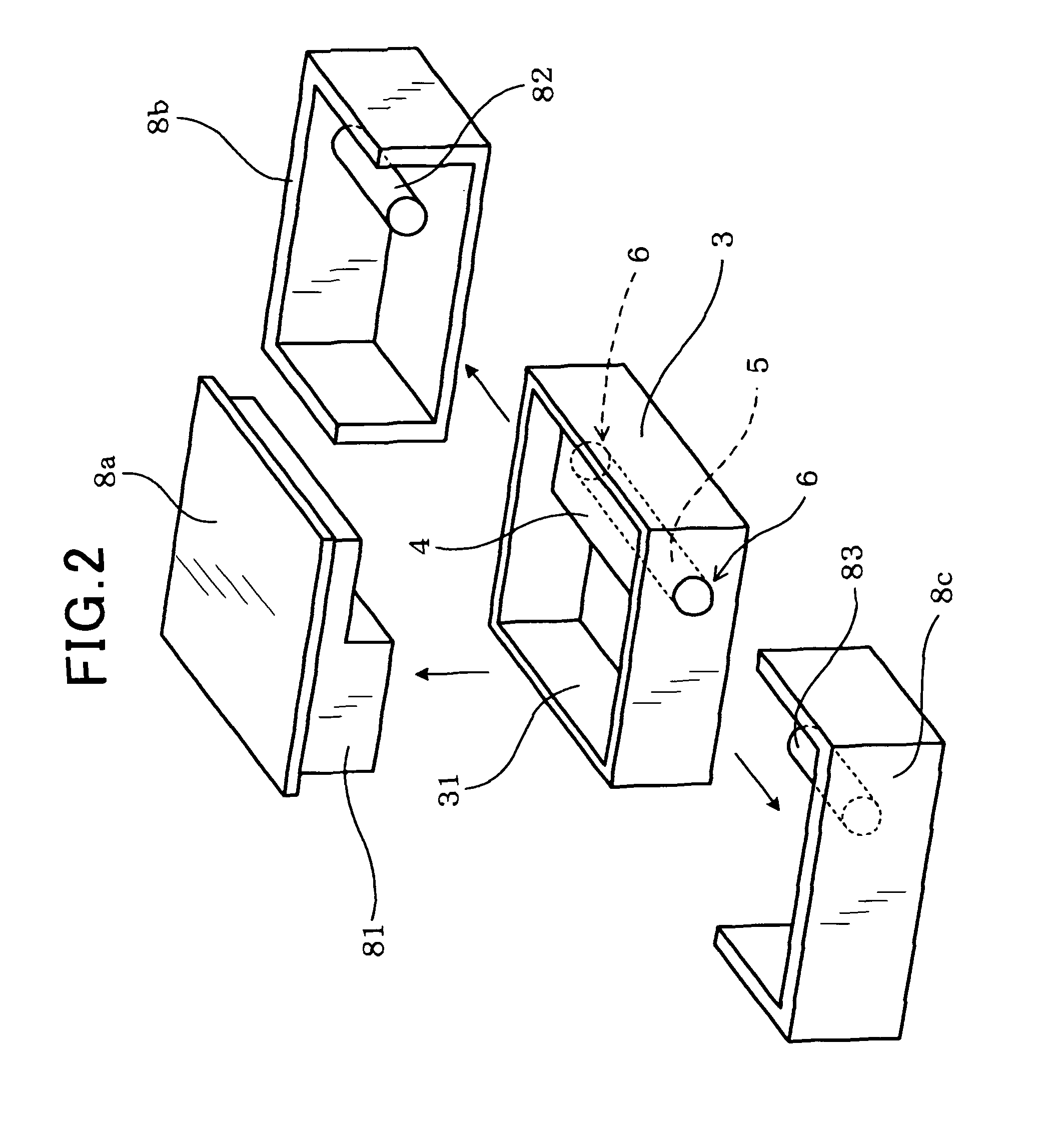
[0090]Referring to FIGS. 6 and 7, hereinafter is described a second embodiment of the present disclosure. FIG. 6 is an explanatory view illustrating a method of manufacturing the casing 3 according to the second embodiment. FIG. 7 is a horizontal cross-sectional view illustrating the casing 3 of the switching power supply 1 according to the second embodiment.
[0091]It should be appreciated that, in the second and the subsequent embodiments, the components identical with or similar to those in the first embodiment are given the same reference numerals for the sake of omitting explanation.
[0092]The second embodiment is different from the first embodiment in that the shape of the coolant channel 5 has been changed.
[0093]As shown in FIG. 7, the coolant channel 5 of the present embodiment includes a primary channel 50 and a secondary channel 51. The primary channel 50 is formed through the seat member 4. The secondary channel 51 is extended in the direction of intersect...
third embodiment
(Third Embodiment)
[0104]Referring to FIG. 8, a third embodiment of the present disclosure is described. FIG. 8 is a horizontal cross-sectional view illustrating the casing 3 of the switching power supply 1 according to the third embodiment.
[0105]As shown in FIG. 8, the coolant channel 5 of the third embodiment includes the primary channel 50 and a pair of secondary channels 51a and 5ab. The primary channel 50 is formed through the seat member 4.
[0106]The pair of secondary channels 51a and 51b is extended in the direction of intersecting the primary channel 50 for connection thereto. The connections are established at the positions between the end portions 6a and 6b of the primary channel 50.
[0107]The secondary channels 51a and 51b each have an end which is open in the outer wall surface 30 of the casing 3. Each of the end portions 6a and 6b of the primary channel 50 is provided with the stopper 7 so that the coolant 10 will flow, for example, from the secondary channel 51a to the se...
PUM
 Abstract
Description
Claims
Application Information