Tool holding module

a tool and module technology, applied in the field of tool holding modules, can solve the problems of inconvenience for users and some problems in the conventional technology, and achieve the effects of improving coupling force and concentricity, preventing the damage or loss of precision of tools, and increasing machining stability

Inactive Publication Date: 2014-09-02
XPOLE PRECISION TOOLS
View PDF37 Cites 11 Cited by
  • Summary
  • Abstract
  • Description
  • Claims
  • Application Information

AI Technical Summary

Benefits of technology

[0005]The primary objective of the present invention is to provide a tool holding module, which increases machining stability via improving the coupling force and concentricity between the fixture seat and the tool rod and can thus prevent a tool from damage or losing precision when the tool is machining a target metal.
[0006]To achieve the abovementioned objective, the present invention proposes a tool holding module, wherein a hollow fixture seat and a hollow tool rod are integrated to form a holding module. The fixture seat has a first outer surface on the external wall thereof, a first top surface on one end thereof, and a fixture head is formed on the same end of the fixture seat. The fixture head has a second outer surface on the external wall thereof and a second top surface on one end thereof. The tool rod and the fixture seat are connected to each other and enfold the fixture head. The internal wall of the tool rod has a first inner surface and a second inner surface respectively corresponding to the first outer surface and the second outer surface. The tool rod also has a first butting surface and a second butting surface inside respectively corresponding to the first top surface and the second top surface. The firmness of the tool holding module is enhanced via the close contact of the first outer surface and first inner surface, the second outer surface and second inner surface, the first top surface and first butting surface, the second top surface and second butting surface. Thereby, the tool holding module of the present invention becomes more secure and robust and can maintain the concentricity between the fixture seat and the tool rod. Therefore, the present invention can prevent the tool from vibration, damage, or falling off and can thus increase machining precision and service life. Besides, the prevent invention also provides various assembly interfaces for different fixture seats and tool rods.

Problems solved by technology

However, the conventional technology still has some problems.
In the conventional technology, the fixing member is used to sleeve the grip member and coupled to the end of the tool rod with a screwing method to enhance the coupling between the grip member and the tool rod; thus, the user has to rotate the fixing member in assembling or disassembling, which inconveniences the user.

Method used


Image

  • Tool holding module
  • Tool holding module
  • Tool holding module

Examples


Embodiment Construction

[0014]Below, the technical contents of the present invention are described in detail in cooperation with the drawings.

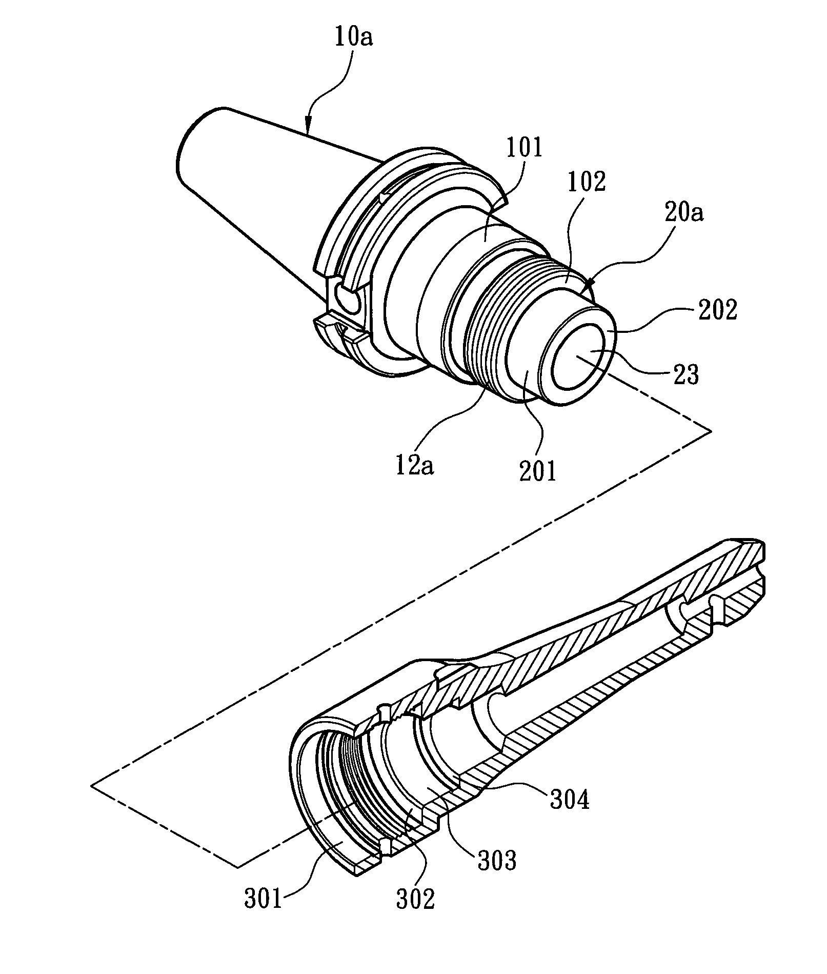
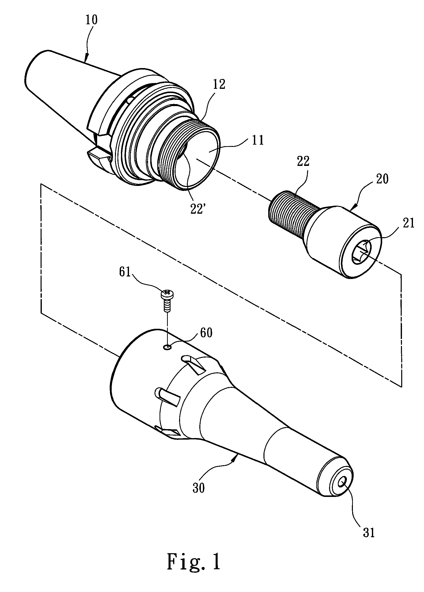
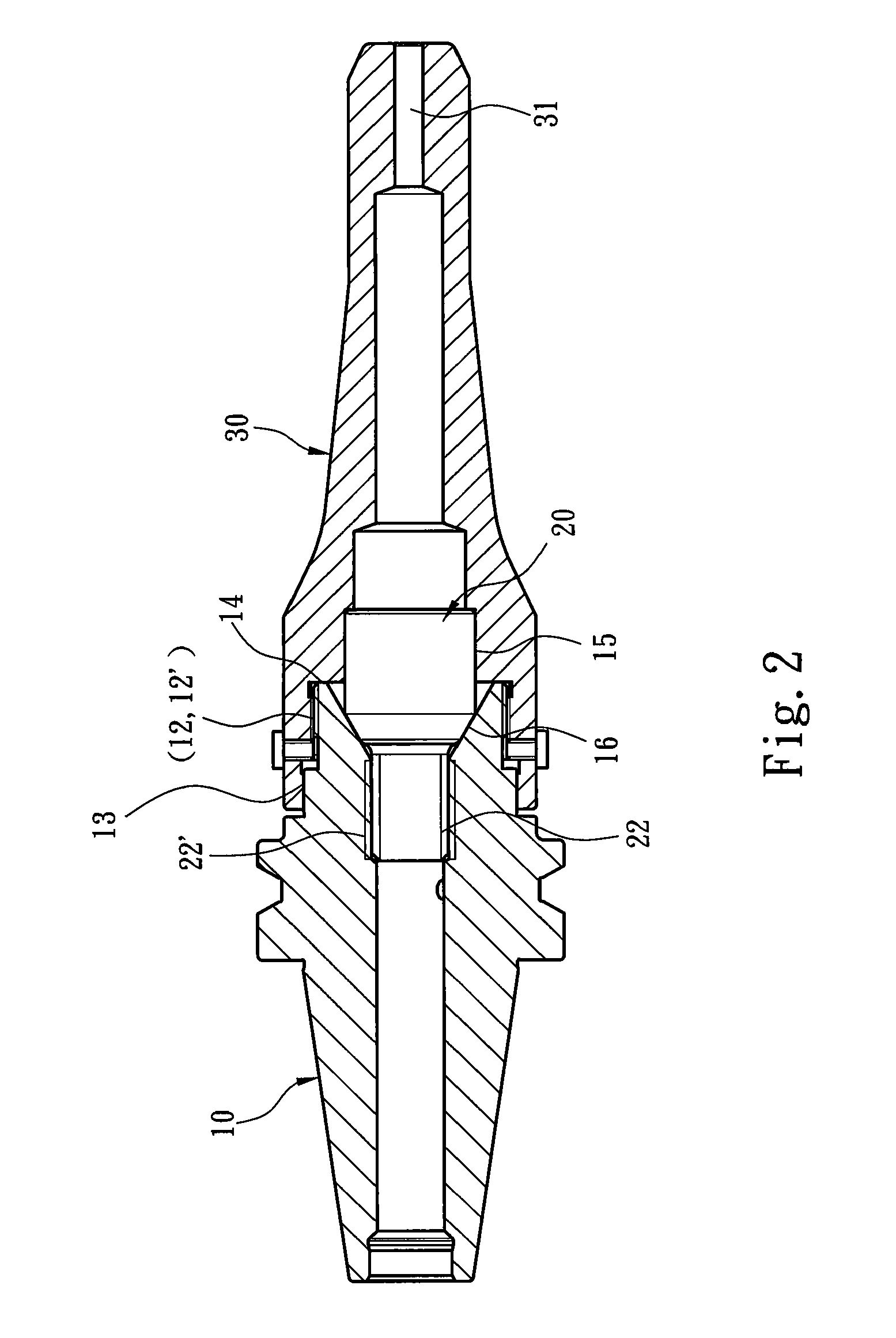
[0015]Refer to FIG. 1 and FIG. 2 respectively a perspective exploded view and a sectional view schematically showing the tool holding module according to one embodiment of the present invention. The present invention is integrated with a driving shaft (not shown in the drawings) and is used to couple a machining cutter or tool to a machining table (not shown in the drawings), wherein the driving shaft of the machining table drives the machining cutter or tool to rotate at a high speed and machine a target workpiece (not shown in the drawings). The tool holding module of the present invention comprises a fixture seat 10 and a tool rod 30. An about pillar-like fixture head 20 is arranged at the connection region of the fixture seat 10 and the tool rod 30. The fixture head 20 is accommodated in a first accommodation room 11 of the fixture seat 10 and enfolded by the too...


PUM

PropertyMeasurementUnit
diameteraaaaaaaaaa
machining stabilityaaaaaaaaaa
outer diameteraaaaaaaaaa

Abstract

A tool holding module comprises a fixture seat and a tool rod. The fixture seat has a first outer surface on an external wall, a first top surface on one end, and a fixture head is located on the same end. The fixture head has a second outer surface on an external wall and a second top surface on one end. The internal wall of the tool rod has first and second inner surfaces respectively corresponding to the first and second outer surfaces, and has first and second butting surfaces respectively corresponding to the first and second top surfaces. The tool rod and fixture seat are connected to enfold the fixture head. The security of the tool holding module is enhanced via close contact of the first outer and inner surfaces, the second outer and inner surfaces, the first top and butting surfaces, the second top and butting surfaces.

Description

[0001]This application is a continuation-in-part, and claims priority, of from U.S. patent application Ser. No. 11 / 812,735 filed on Jun. 21, 2007, now abandoned entitled “TOOL HOLDING MODULE”.FIELD OF THE INVENTION[0002]The present invention relates to a tool holding module, particularly to a tool holding module which can promote machining stability.BACKGROUND OF THE INVENTION[0003]At present, high-precision metal machining, such as drilling, reaming, boring, thread milling, inner / outer diameter drilling, or surface grinding, is usually processed by a CNC (Computer Numerical Control) machining table together with various cutters or tools. A cutter or tool has a long handle gripped by a gripper or a grip mechanism, whereby the cutter or tool can be coupled to a driving shaft of a CNC table. Thus, the driving shaft rotating at a high speed can drive the cutter or tool gripped by a gripper to machine a target workpiece.[0004]A R.O.C. patent No. M253434 disclosed a “Detachable Tool Fixt...

Claims


Application Information

Patent Timeline
Patent Type & Authority Patents(United States)
IPC IPC(8): B23B31/08B23B31/10B23B31/02B23B31/11B23B31/20
CPCB23B31/02B23B31/11B23B31/20B23B2270/12B23B2260/016Y10T279/17504Y10T279/3406Y10T409/309408Y10T409/30952B23B31/2012
Inventor CHEN, PETER
Owner XPOLE PRECISION TOOLS
Why Eureka
Try Eureka