Universal serial bus connector

a universal serial bus and connector technology, applied in the direction of coupling device connection, two-part coupling device, electrical apparatus, etc., can solve the problems of unsteady soldering of the core wires of the cable with the soldering portions of the terminal, and affect the soldering quality of the universal serial bus connector

Inactive Publication Date: 2014-09-02
CHENG UEI PRECISION IND CO LTD
View PDF9 Cites 14 Cited by
  • Summary
  • Abstract
  • Description
  • Claims
  • Application Information

AI Technical Summary

Benefits of technology

[0007]As described above, the soldering portions which slantwise extends upward and rearward of the terminals abut against the upward and rearward inclined resisting surfaces of the dielectric base which are arranged in the plurality of parallel rows and in a stair shape, and the first main board of the lower shell and the second main board of the upper shell are parallel with the soldering portions of the terminals abutting against the resisting surfaces of the dielectric base. Thus, the soldering portions of the terminals soldered steadily and soldering areas of the soldering portions of the terminals are enlarged accordingly for effectively ensuring a soldering quality of the soldering portions of the terminals of the universal serial bus connector.

Problems solved by technology

However, in the process of the core wires of the cable being soldered with the soldering portions of the terminals, the soldering portions of the terminals are apt to sway that makes the core wires of the cable be soldered with the soldering portions of the terminals unsteadily.
As a result, a soldering quality of the universal serial bus connector is affected.

Method used


Image

  • Universal serial bus connector
  • Universal serial bus connector
  • Universal serial bus connector

Examples


Embodiment Construction

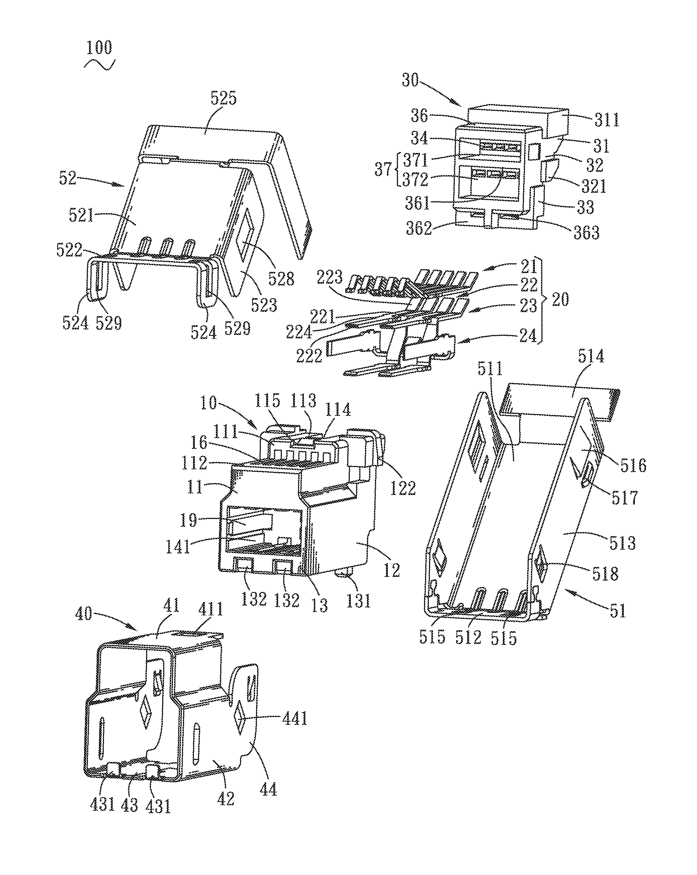
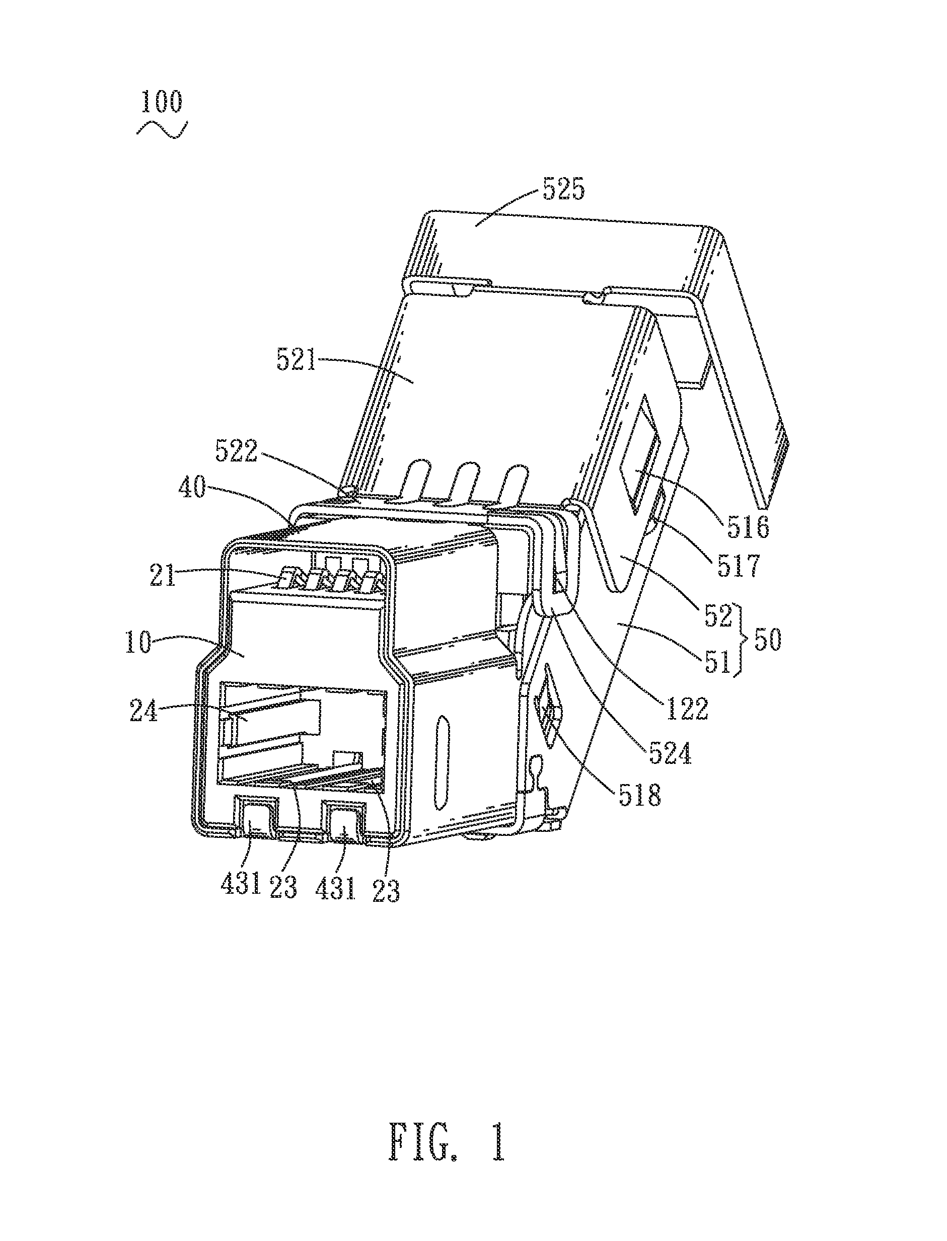
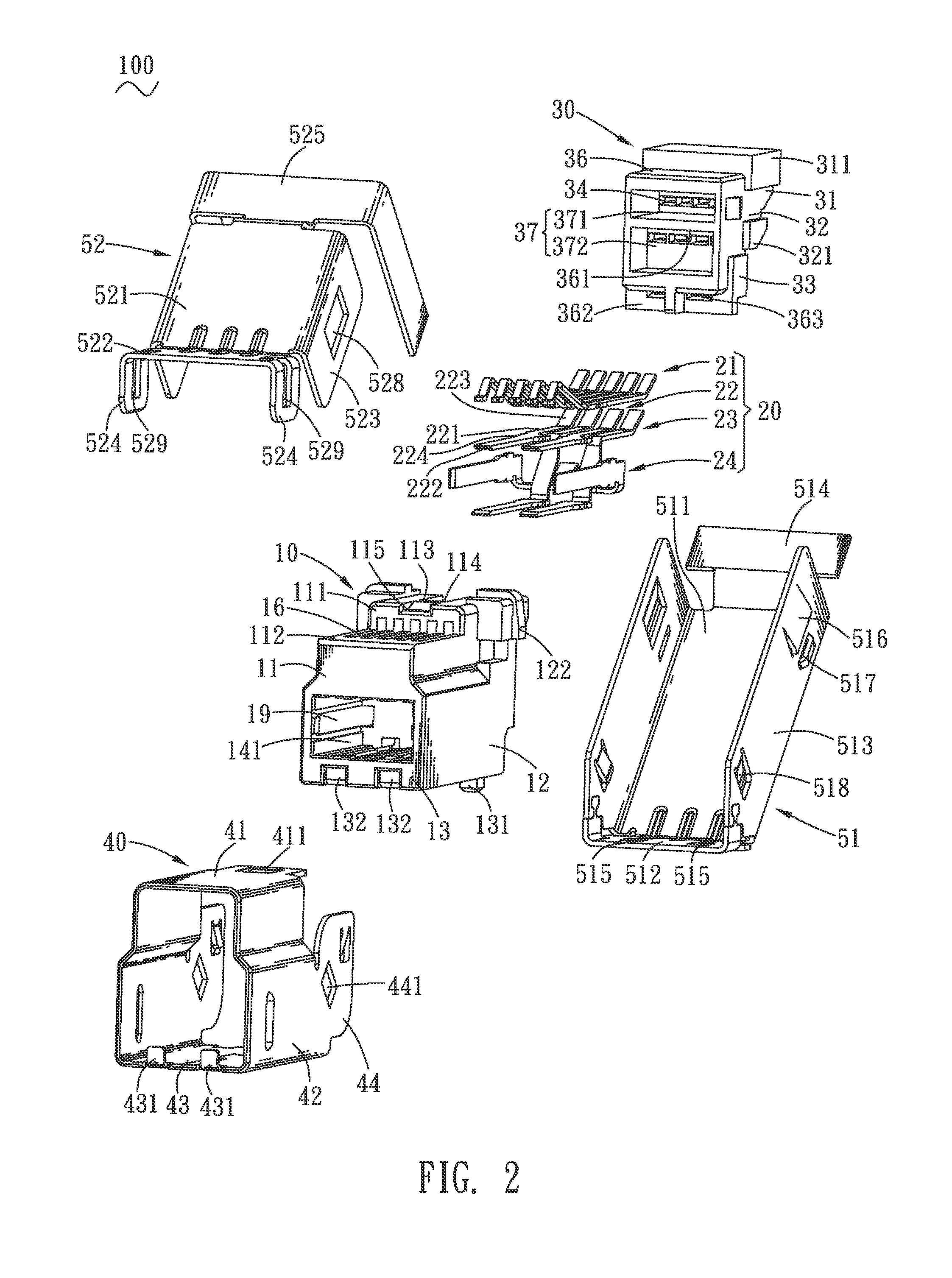
[0014]With reference to FIG. 1 and FIG. 2, an universal serial bus connector 100 in accordance with the present invention is shown. The universal serial bus connector 100 includes an insulating housing 10, a plurality of terminals 20, a dielectric base 30, a first shielding shell 40 and a second shielding shell 50.

[0015]Referring to FIG. 2, FIG. 3 and FIG. 5, the insulating housing 10 has a top wall 11, two side walls 12 extending downward from two opposite sides of the top wall 11, and a bottom wall 13 connecting with two bottoms of the two side walls 12. A receiving space 14 is formed among the top wall 11, the two side walls 12 and the bottom wall 13. Inner surfaces of the top wall 11, the two side walls 12 and the bottom wall 13 are connected with a connecting wall 15. The receiving space 14 is divided into a first receiving space 141 and a second receiving space 142 by the connecting wall 15. The top wall 11 includes a rectangular base body 111, a first base board 112 extending...


PUM


Abstract

A universal serial bus connector includes an insulating housing, a plurality of terminals disposed to the insulating housing, a dielectric base, a first shielding shell surrounding the insulating housing, and a second shielding shell. Each of the terminals has a fastening portion, and a soldering portion slantwise extending upward and rearward from a rear end of the fastening portion to be exposed behind the insulating housing. The dielectric base disposed to a rear end of the insulating housing defines a plurality of rows of insertion slots and resisting surfaces exposed behind the insulating housing. The soldering portions are inserted into the insertion slots and abut against the resisting surfaces. The second shielding shell disposed to rear ends of the insulating housing and the first shielding shell includes a first main board and a second main board parallel with the soldering portions abutting against the resisting surfaces.

Description

BACKGROUND OF THE INVENTION[0001]1. Field of the Invention[0002]The present invention generally relates to a connector, and more particularly to a universal serial bus connector.[0003]2. The Related Art[0004]In recent years, with the rapid development of economy, people's daily lives have been significantly improved. In order to satisfy people's growing needs of material culture lives, a variety of electronic products and peripheral devices are used in the people's daily lives. As is known to all, universal serial bus connectors are common-used components of the electronic products and the peripheral devices. Generally, the universal serial bus connector includes an insulating housing, a plurality of terminals, and a shielding shell surrounding the insulating housing. The insulating housing defines a receiving space penetrating through a front thereof, and a plurality of terminal grooves. Each of the terminal grooves penetrates through a rear thereof and communicates with the receiv...

Claims


Application Information

Patent Timeline
Patent Type & Authority Patents(United States)
IPC IPC(8): H01R27/02H01R13/6591H01R13/514H01R13/60
CPCH01R13/60H01R27/02H01R13/514H01R24/62H01R13/6591H01R13/6581
Inventor LAN, RONG, QIN
Owner CHENG UEI PRECISION IND CO LTD
Why Eureka
Try Eureka