Joint for connecting buckling-restrained brace, concrete beam and concrete column

A technology for concrete beams and concrete columns, which is applied in building components, earthquake resistance, construction, etc., can solve problems such as poor stability, reduced strength, and pullout failure of anchor bars, and achieve high stability and rigidity. The effect of stress concentration

Inactive Publication Date: 2015-04-29
SHENYANG JIANZHU UNIVERSITY
View PDF5 Cites 12 Cited by
  • Summary
  • Abstract
  • Description
  • Claims
  • Application Information

AI Technical Summary

Problems solved by technology

The disadvantage of this kind of joint is: the whole steel plate cuts the concrete beam and column into two halves, which weakens the integrity of the concrete beam and column and reduces the strength; Concrete beams and columns are split; when tying concrete beams and column stirrups, the steel plate becomes an obstacle, making construction inconvenient
The disadvantages of this kind of joint are: the symmetry and stability of the angle steel are poor; the welding area between the angle steel and the anchor plate is small, and it is easy to cause drawing damage during the stress process; the contact force transmission area between the angle steel and concrete is small, and the joint strength is poor
The disadvantages of this kind of joint are: the stability of the anchor bar is poor; the welding area between the anchor bar and the anchor plate is small, and it is easy to produce pullout damage during the stress process; the contact force transmission area between the anchor bar and the concrete is small, and the joint strength is poor

Method used


Image

  • Joint for connecting buckling-restrained brace, concrete beam and concrete column
  • Joint for connecting buckling-restrained brace, concrete beam and concrete column

Examples


Embodiment Construction

[0021] The present invention will be further described below in conjunction with drawings and embodiments.

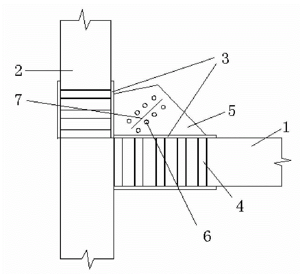
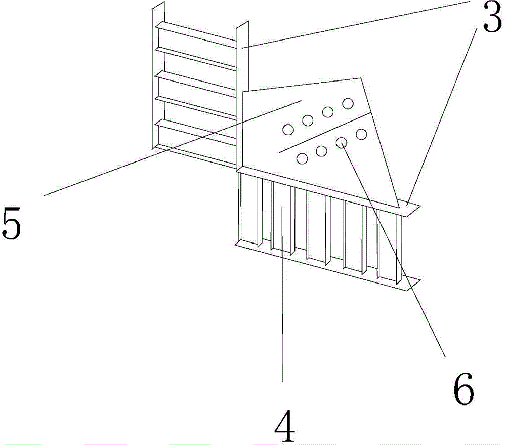
[0022] to combine figure 1 and figure 2 In this embodiment, the connection node between the buckling-constrained support and the concrete beam and column is composed of anchors anchored in the concrete beam 1 and concrete column 2 and a gusset plate 5 placed outside the concrete beam and concrete column. The anchor piece anchored in the concrete beam 1 is composed of three H-shaped steels 4 spaced apart from each other, and the anchor piece anchored in the concrete column 2 is composed of five H-shaped steels 4 spaced apart from each other. 3 are welded together, the inner edge of the anchor plate 3 is on the outside of the concrete beam 1 and the concrete column 2; The outer end of the anchor plate welded integrally with the gusset plate is 100mm longer than the side of the gusset plate; bolt holes 6 for buckling restraint support and fixed connection are processed ...


PUM


Abstract

The invention discloses a joint for connecting a buckling-restrained brace, a concrete beam and a concrete column; an anchoring part anchored in the concrete beam and the concrete column is composed of two groups of spaced H-shaped profile steels; the H-shaped profile steels and an anchoring plate are welded into a whole one; the internal edge of the anchoring plate id arranged at the external sides of the concrete beam and the concrete column; a joint plate is integrally welded with the anchoring plate; the external end of the anchoring plate integrally welded with the joint plate is lengthened to be longer than the lateral side of the joint plate; and bolt holes for fixing the buckling-restrained brace are formed on the joint plate. The H-shaped profile steels in the joint plate have good stability in a plane and high rigidness and are not easy in instability; the profile steels have big welded areas with the anchoring plate and are not easy to produce pulling / pushing damage; the profile steels have big contact and load-transfer areas with the concrete and are capable of uniformly dispersing the load to the concrete beam; the lengthened parts at two ends of the anchoring plate are capable of effectively avoiding direct extrusion between the joint plate and the concrete, so that the stress concentration is relieved and the service life of the joint is prolonged; the integrality of the concrete beam and the concrete column is not influenced, so that hoops and longitudinal ribs in the concrete beam can be arranged easily; the steel ratio in the joint area of the beam and the column is increased and the strength and rigidness of the joint is improved by the plastic deformation of the beam restrained by the anchoring plate; the whole component can be manufactured in a factory and the construction time is saved.

Description

technical field [0001] The invention relates to a building structure, in particular to a connection node between a buckling-constrained support and a concrete beam and column. Background technique [0002] Concrete frame structures with buckling-restrained braces are being popularized and applied in the field of construction due to their advantages in seismic performance, simple construction, and saving raw materials. Among them, the connection node between the buckling restraint support and the concrete frame is a very important link in the whole structure, which requires sufficient strength, appropriate stiffness, and sufficient rotation capacity to transmit shear force and bending moment reasonably; at the same time, it should be easy to manufacture and convenient construction. A good node should conform to the design principle of "strong node, weak component". [0003] The existing buckling-restrained braces and concrete beams and columns are as follows: [0004] One ...

Claims


Application Information

Patent Timeline
Patent Type & Authority Applications(China)
IPC IPC(8): E04B1/58E04B1/98
Inventor 李帼昌管德鹏杨志坚
Owner SHENYANG JIANZHU UNIVERSITY
Why Eureka
Try Eureka