Construction method for steel bar work down electro-slag pressure welding

A technology of electroslag pressure welding and construction method, which is applied in the direction of arc welding equipment, manufacturing tools, welding equipment, etc., and can solve the problems of low carbon equivalent, low efficiency, and poor quality

Inactive Publication Date: 2008-08-20
XINPU CONSTR GRP
View PDF0 Cites 10 Cited by
  • Summary
  • Abstract
  • Description
  • Claims
  • Application Information

AI Technical Summary

Problems solved by technology

[0003] In view of the above situation, the purpose of the present invention is to provide a HRB500 steel upsetting electroslag pressure welding construction method, which can effectively solve the problems of troublesome welding of steel bars, low efficiency and poor quality. Upsetting, increasing the welding area, and then placing the two steel bars in a vertical butt joint form, using a welding machine to make the welding current pass through the gap between the upsetting end faces of the two steel bars, forming an arc process and an electroslag process under the flux layer, generating arc heat and resistance heat, melt the steel bars, and longitudinally pressurize the two steel bars, so that the two steel bars are tightly combined. After cooling down, the two steel bars are firmly connected together by welding. The invention has advanced technology, simple operation, good welding quality and high speed. Fast, high efficiency, HRB500 steel bar has high strength, good ductility, low carbon equivalent, good weldability, low price, saves steel, not only reduces the effect of steel bar section in concrete components, but also improves the bearing capacity of components, convenient construction, no Environmental pollution is a great invention in steel welding, with huge economic and social benefits

Method used


Image

  • Construction method for steel bar work down electro-slag pressure welding
  • Construction method for steel bar work down electro-slag pressure welding
  • Construction method for steel bar work down electro-slag pressure welding

Examples


Embodiment Construction

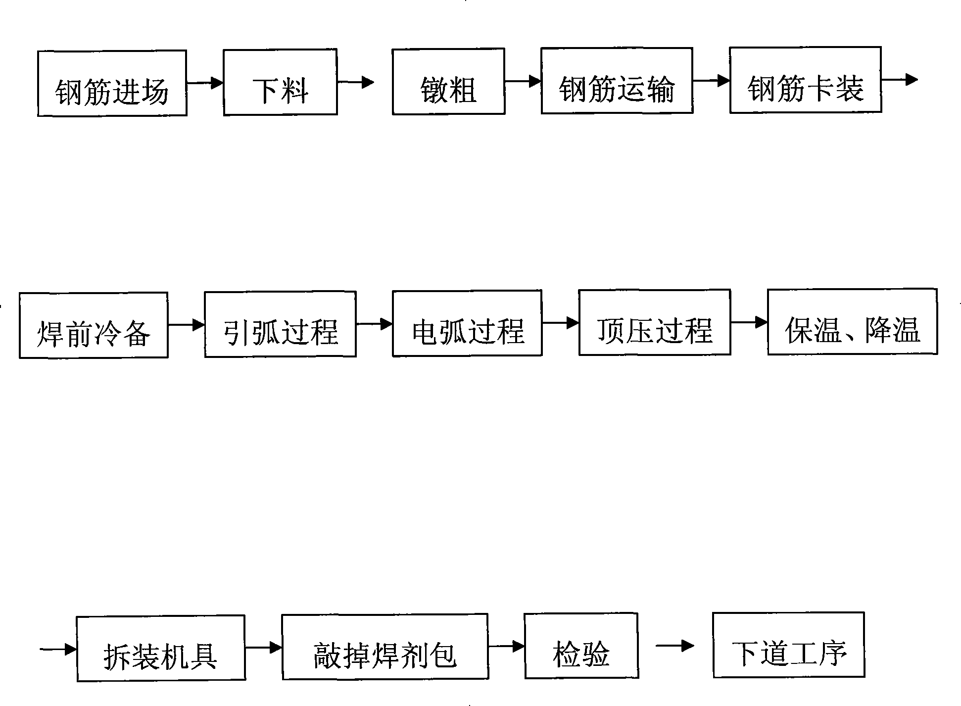
[0005] The present invention will be described in detail below in conjunction with the process flow diagram. Given by the process flow chart, the construction method of the present invention is as follows: after the steel bar enters the site and is unloaded, the end of the steel bar is upset by the upsetting machine into a welding plane, and then transported to the steel bar clamping machine, and the two welded steel bars are vertically clamped. Install it on the clamping machine so that the ends of the two steel bars are in the form of butt joint, the two ends are not connected, and they are in a disconnected state. Make preparations before welding, then turn on the power, use the AC arc welding machine to start the arc, and the arc welding machine will weld The pliers clamp the upper and lower steel bars respectively, turn on the power supply, and after applying the welding voltage to the upper and lower steel bars, quickly lift the upper steel bar so that the distance betwee...


PUM


Abstract

The invention relates to a method of steel bar upsetting electroslag pressure welding. First, the steel bar head is upset thick to enlarge the welding area. Then two steel bars are positioned in a vertical docking form. The welding current passes through space between two steel bar upsetting ends by use of a welding machine to form an electric arc process and an electroslag process under the welding flux layer. The electric arc heat and the resistance heat are produced and the steel bars are melted. Then vertical pressure is reinforced on two steel bars so that two steel bars are combined together. After cooling, two steel bars are fixedly connected with each other through a welding package. The method of steel bar upsetting electroslag pressure welding has the advantages that the craft is advanced; the operation is easy; the welding quality is good; HRB500 steel bar has high strength, good ductility, low carbon equivalence, and good weldability; steels are save; the function of the steel bar section in the concrete means is reduced; the bearing capacity of the means is improved; the construction is convenient; and the environmental pollution is avoided. The method has also the advantages of solving problems of complicated welding, low efficiency, and poor quality, being a great invention in the technology of steel bar welding, and having huge economic and social benefits.

Description

1. Technical field [0001] The invention relates to the field of construction, in particular to a construction method of electroslag pressure welding for upsetting HRB500 steel bars. 2. Background technology [0002] With the rapid development of the economy, the construction industry is also advancing rapidly, and various buildings have sprung up everywhere, especially high-rise buildings can be seen everywhere, but in the construction of high-rise buildings, the welding of steel bars is essential, Steel bar welding is the most commonly used connection technology in construction engineering. The quality of the welding directly affects the quality and progress of the building. As a new building material, HRB500 steel bars are widely used in construction. There are welding defects in pressure welding, such as undercut around the steel bar, which weakens the effective area of ​​steel bar welding, and the contact area of ​​the two steel bar joints is very small, which is trouble...

Claims


Application Information

Patent Timeline
Patent Type & Authority Applications(China)
IPC IPC(8): B23K28/02B23K9/095B23K25/00B23K9/235
Inventor 王麦对刘轶王旭风王建强刘昊纯
Owner XINPU CONSTR GRP
Why Eureka
Try Eureka