
Surgical filament snare assemblies

a technology of filament snares and filament snares, which is applied in the field of surgical filament snare assemblies, can solve the problems of reducing requiring additional knots, and requiring loops to be expanded, so as to reduce the number of half hitches or other knots

Active Publication Date: 2014-09-02
MEDOS INT SARL
View PDF252 Cites 91 Cited by
  • Summary
  • Abstract
  • Description
  • Claims
  • Application Information

AI Technical Summary

Benefits of technology

The present invention is a surgical filament snare assembly for tissue repair procedures. The assembly includes an anchor capable of being fixated in bone and a filament engagement feature. The assembly allows for easier tensioning of tissue with reduced knots and half hitches. The assembly also reduces the size of the finished knot and simplifies the overall knot tying process for the surgeon. The technical effects of the invention are efficient and effective tissue repair while minimizing the impact on the patient.

Problems solved by technology

The additional knots are needed because a conventional sliding knot does not provide the necessary protection against loosening or slippage, especially when tension is placed primarily on the limbs of the loop.
Before one or more half hitches or other knots can be added to the sliding knot, however, there exists a potential for the sliding knot to slip, that is, for the loop to enlarge as the tissue places tension on the loop.
Sometimes, even fully-tied knots may slip.
Further, the overall size of a conventional knot can be obstructive or intrusive, especially in tight joints, which may damage cartilage or other tissue by abrasion with the knot.

Method used


Image

  • Surgical filament snare assemblies
  • Surgical filament snare assemblies
  • Surgical filament snare assemblies

Examples


Embodiment Construction

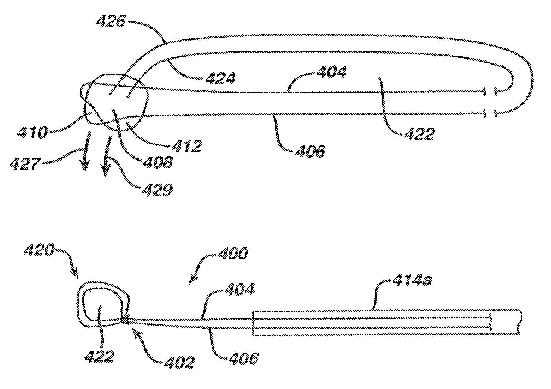
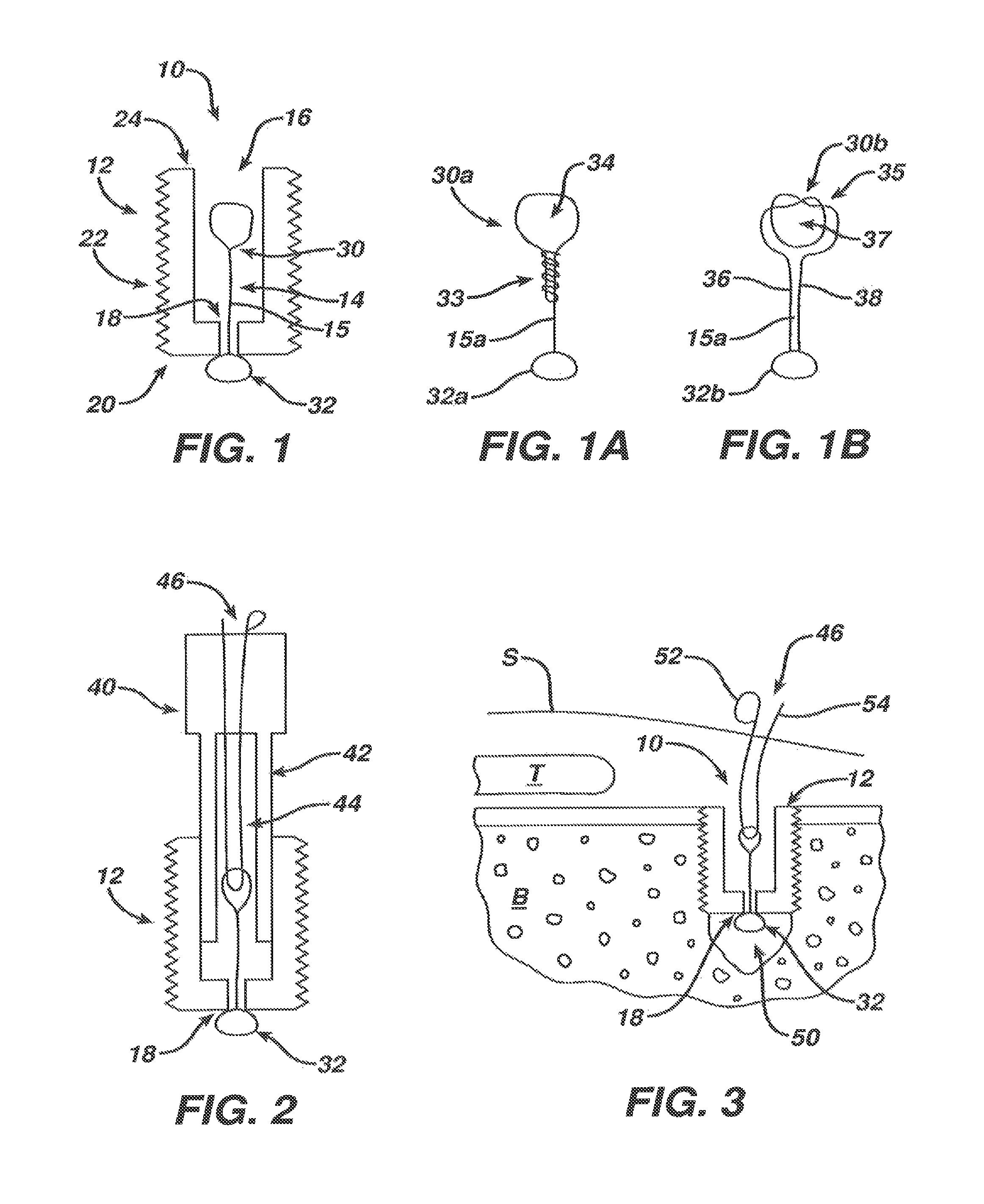
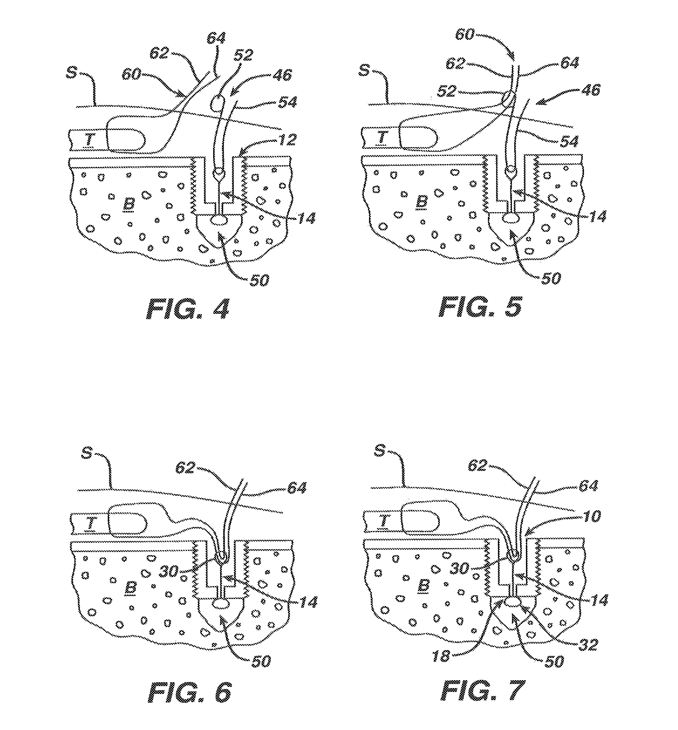
[0054]This invention may be accomplished by a surgical filament snare assembly including an anchor capable of being fixated in bone and having a filament engagement feature. A first filament has a noose, or a loop capable of being formed into a noose, on a first, proximal portion of at least a first limb and has a second portion connected, including slidably or fixedly connected, directly or indirectly, to the filament engagement feature of the anchor. The noose, such as one or more half-hitches, a Lark's Head knot, or a hangman-type noose, is capable of receiving at least one end of a free filament limb or a portion of another filament. The noose strangulates the free filament limb or other filament when tension is applied to the noose, to the free filament limb, and / or to the other filament.

[0055]In certain preferred constructions, at least a first free filament limb, which in some constructions is a length of the first filament and in other constructions is a second filament, is ...


PUM


Abstract

A surgical filament snare assembly including an anchor capable of being fixated in bone and having a filament engagement feature. A first filament has a noose with first and second noose limbs connected, preferably slidably, to the filament engagement feature. The first and second noose limbs emerge from the anchor as first and second free filament limbs that are capable of being passed through tissue to be repaired and then passable through the noose. The noose is capable of receiving the free filament limbs and strangulating them when tension is applied to at least one of the free filament limbs and the noose to enable incremental tensioning of the tissue after anchor fixation. Preferably, the snare assembly further includes a flexible sleeve joining at least some portion of the first and second free filament limbs to facilitate passing of the free filament limbs as a single unit.

Description

CROSS-REFERENCE TO RELATED APPLICATIONS[0001]This application claims priority to U.S. patent application Ser. No. 13 / 218,810 filed Aug. 26, 2011, which is a continuation in part of U.S. patent application Ser. No. 12 / 977,154 filed Dec. 23, 2010, which is a non-provisional of U.S. Provisional Application No. 61 / 416,562 filed Nov. 23, 2010, each of which is incorporated by reference in its entirety, U.S. patent application Ser. No. 13 / 218,810 filed Aug. 26, 2011, is also a continuation in part of U.S. patent application Ser. No. 12 / 977,146 filed Dec. 23, 2010, which is incorporated by reference in its entirety.BACKGROUND OF THE INVENTION[0002]1. Field of the Invention[0003]The invention relates to filament assemblies for securing tissue to bone and more particularly to adjustable tensioning of tissue independent of anchor fixation.[0004]2. Description of the Related Art[0005]A common injury, especially among athletes, is the complete or partial detachment of tendons, ligaments or othe...

Claims


Application Information

Patent Timeline
Patent Type & Authority Patents(United States)
IPC IPC(8): A61B17/04
CPCA61B2017/044A61B17/0485A61B2019/4836A61B17/0482A61B2017/0458A61B2017/0475A61B2017/0448A61B2017/0464A61B2017/0456A61B17/0401A61B17/06166A61B2017/06185A61B2090/0807A61B2017/0414A61B2017/0445
Inventor SENGUN, MEHMET ZIYATANG, HOWARDSPENCINER, DAVID B.
Owner MEDOS INT SARL
Learn More