Switching apparatus

a technology of switching apparatus and cam means, which is applied in the direction of electric switches, contact driving mechanisms, electric switches, etc., can solve the problems of complicated mechanism, high cost and time-consuming assembly, and achieve the effect of rapid acceleration and retardation, and relatively low weight of cam means

Active Publication Date: 2014-09-02
HITACHI ENERGY SWITZERLAND AG
View PDF17 Cites 3 Cited by
  • Summary
  • Abstract
  • Description
  • Claims
  • Application Information

AI Technical Summary

Benefits of technology

[0010]The invented bistable mechanism consists of less parts than the known device and is much easier and faster to assemble. Further the use of a cam allows a greater freedom to optimize the performance of the switching apparatus simply by shaping the profile of the cam accordingly. Another benefit is that the diameter of the housing can be much smaller since the means for urging each cam follower against the cam requires less radial space than the springs in the device according to prior art, which have to be dimensioned to allow the rods to move from the inclined position to the radial position. This is of particular interest for a switching device with a large stroke length. The use of a cam device as the bistable mechanism also has the advantage that the characteristic of the actuation movement can be freely tailored to be adapted to different needs for various applications simply by shaping the cam profile accordingly, whereas a toggle device has more limited flexibility in this respect.
[0036]Thereby the weight of the cam means can be kept relatively low in comparison with a cam means made as a common part for all cam followers with a cam profile extending entirely around the axis. A low weight is important in order to allow as rapid acceleration and retardation as possible during actuation. The separate cam units might be constituted by one single plate-shaped piece or by separate pieces attached together or to the actuating means.

Problems solved by technology

Although the known bistable mechanism normally functions satisfactory it has some drawbacks.
The mechanism is complicated, expensive and also time consuming to assemble.
This could be a problem because the insulator housing of a switching apparatus might be quite large as it is today, and a still larger insulator might be needed for a larger stroke.

Method used


Image

  • Switching apparatus
  • Switching apparatus
  • Switching apparatus

Examples


Embodiment Construction

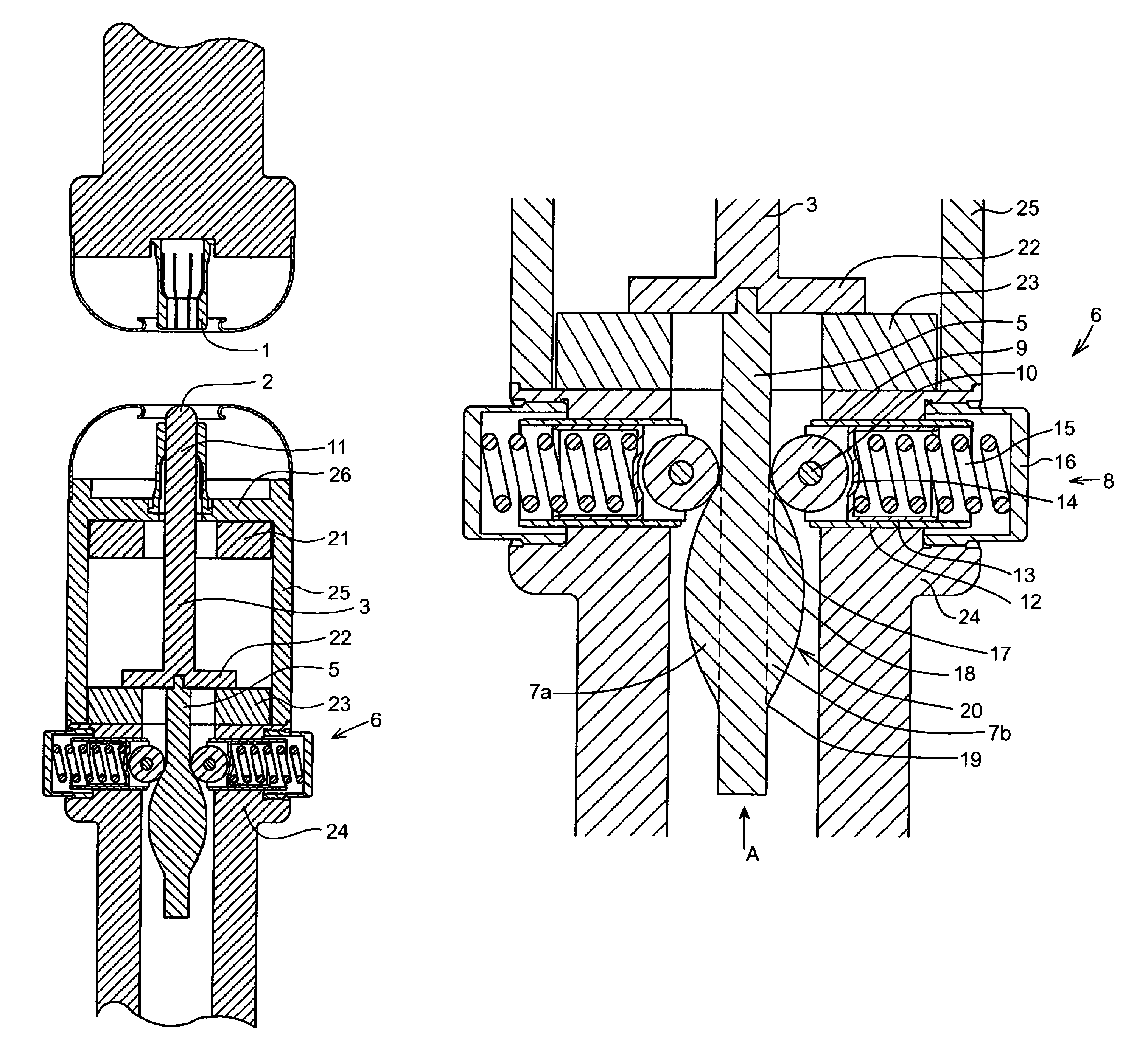
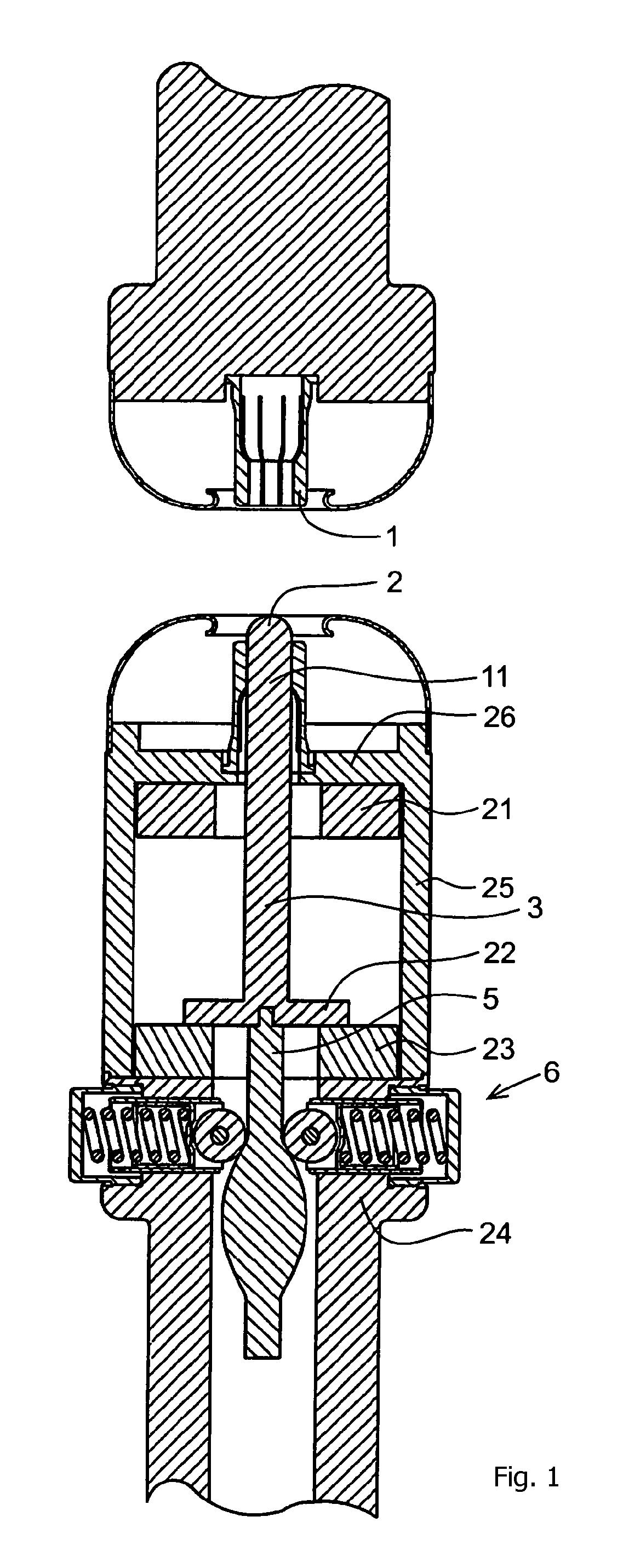
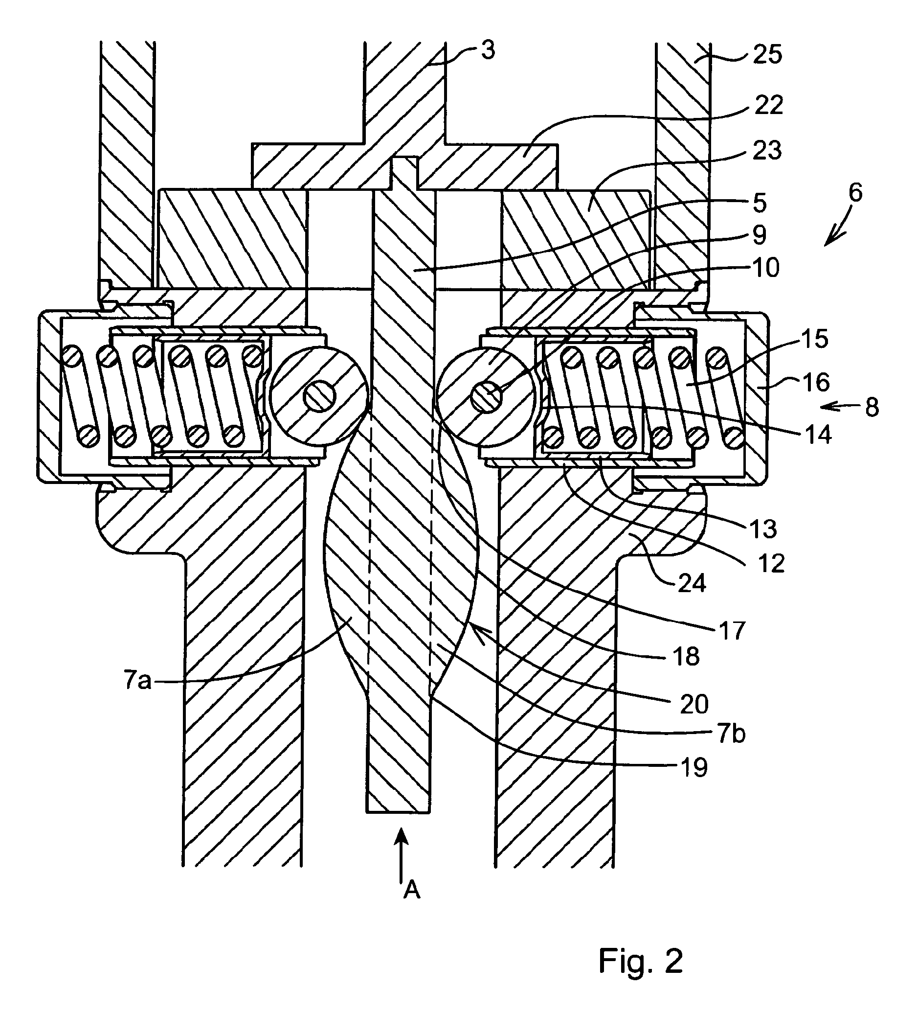
[0046]FIG. 1 illustrates a switching apparatus provided with a bistable mechanism according to the invention. The illustration is simplified for the sake of clarity in order to focus on the aspects that are relevant for the understanding of the invention. Thus details like the conductors and the insulation are left out. These details can be of any conventional kind and do not require to be described. The switching apparatus has a stationary contact part 1 and a movable contact part 2. The movable contact part 2 is arranged as the upper end of a first rod 3. The lower end of the rod 3 is attached to a plate 22 of conductive material. From the underside of the plate 22 a second rod 5 extends downward. The second rod 5 is arranged to cooperate with a bistable mechanism that will be described further below. In this example the first rod 3 is made integrated with the plate 22, but they might alternatively be made of separate pieces. Also the second rod 5 might alternatively be integrated...


PUM


Abstract

A switching apparatus for closing and / or opening an electric circuit. It has an actuating unit and a bistable mechanism. The actuating unit is linearly movable between a first end position in which the switching apparatus is in a closed state and a second end position in which the switching apparatus is in an open state. The linear movement defines an axis. The bistable mechanism is arranged to ensure that the actuating unit is held in either of the end positions. The bistable mechanism includes a cam means mechanically connected to the actuating unit and at least one cam follower. The invention also relates to a use of the invented apparatus.

Description

FIELD OF THE INVENTION[0001]The present invention relates to a switching apparatus for closing and / or opening an electric circuit and including an actuating unit and a bistable mechanism, the actuating unit being linearly movable between a first end position in which the switching apparatus is in a closed state and a second end position in which the switching apparatus is in an open state, which linear movement defines an axis, the bistable mechanism being arranged to ensure that the actuating unit is held in either of the end positions.[0002]Terms like “radial”, “axial” and “circumferential” in the text of the present application refer to the defined axis.BACKGROUND OF THE INVENTION[0003]The switching apparatus might be a closer for quick closing an electric circuit, in particular of the medium or high voltage level. Such a switching apparatus normally has two contacts movable to and from each other. Usually the movement is linear. The relative movement can either be achieved in th...

Claims


Application Information

Patent Timeline
Patent Type & Authority Patents(United States)
IPC IPC(8): H01H15/24H01H3/50H01H9/20
CPCH01H9/20H01H3/50
Inventor BORG, TOMASJOHANSSON, DANIEL
Owner HITACHI ENERGY SWITZERLAND AG
Why Eureka
Try Eureka