
Radiation treatment planning system

a technology of radiation treatment and planning system, applied in the field of radiation treatment planning system, can solve the problems of significant increase in calculation time and increase in iterative calculation load, and achieve the effect of reducing tim

Active Publication Date: 2014-09-02
HITACHI LTD
View PDF6 Cites 3 Cited by
  • Summary
  • Abstract
  • Description
  • Claims
  • Application Information

AI Technical Summary

Benefits of technology

[0013]As discussed above, the spot irradiation dose search method, proposed in Non-Patent Document 1, requires calculating the objective function from the dose matrix with each search for the spot irradiation dose. In the scanning irradiation methods, on the other hand, the beam size increases because of the influence of the nuclear reactions in water or scattering inside the irradiation system (source: Non-Patent Document 2). The increase in the beam size accordingly increases non-zero elements in the dose matrix used for the irradiation dose search, thus causes an increase in the load of iterative calculation and hence in a significant increase in calculation time.
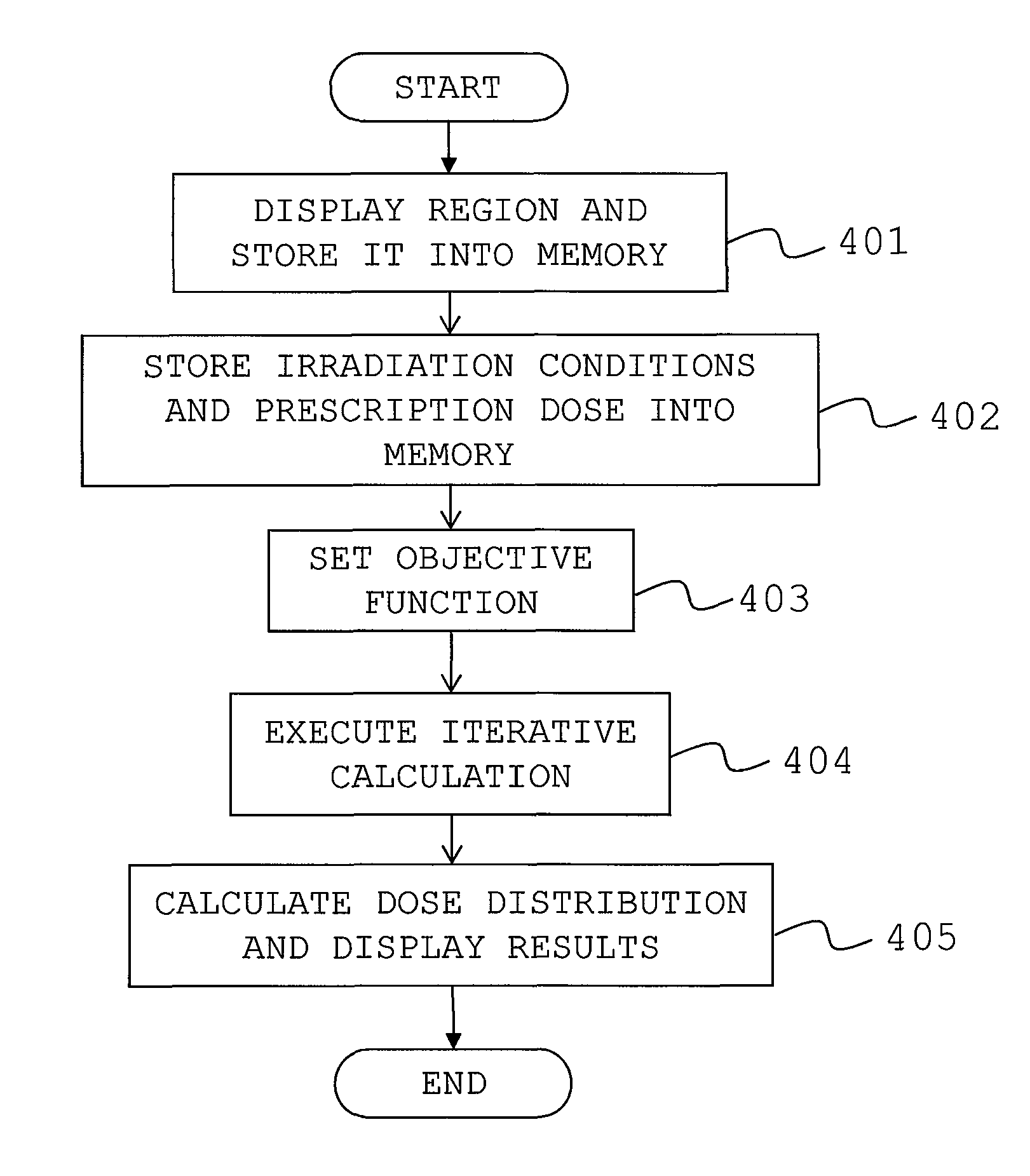
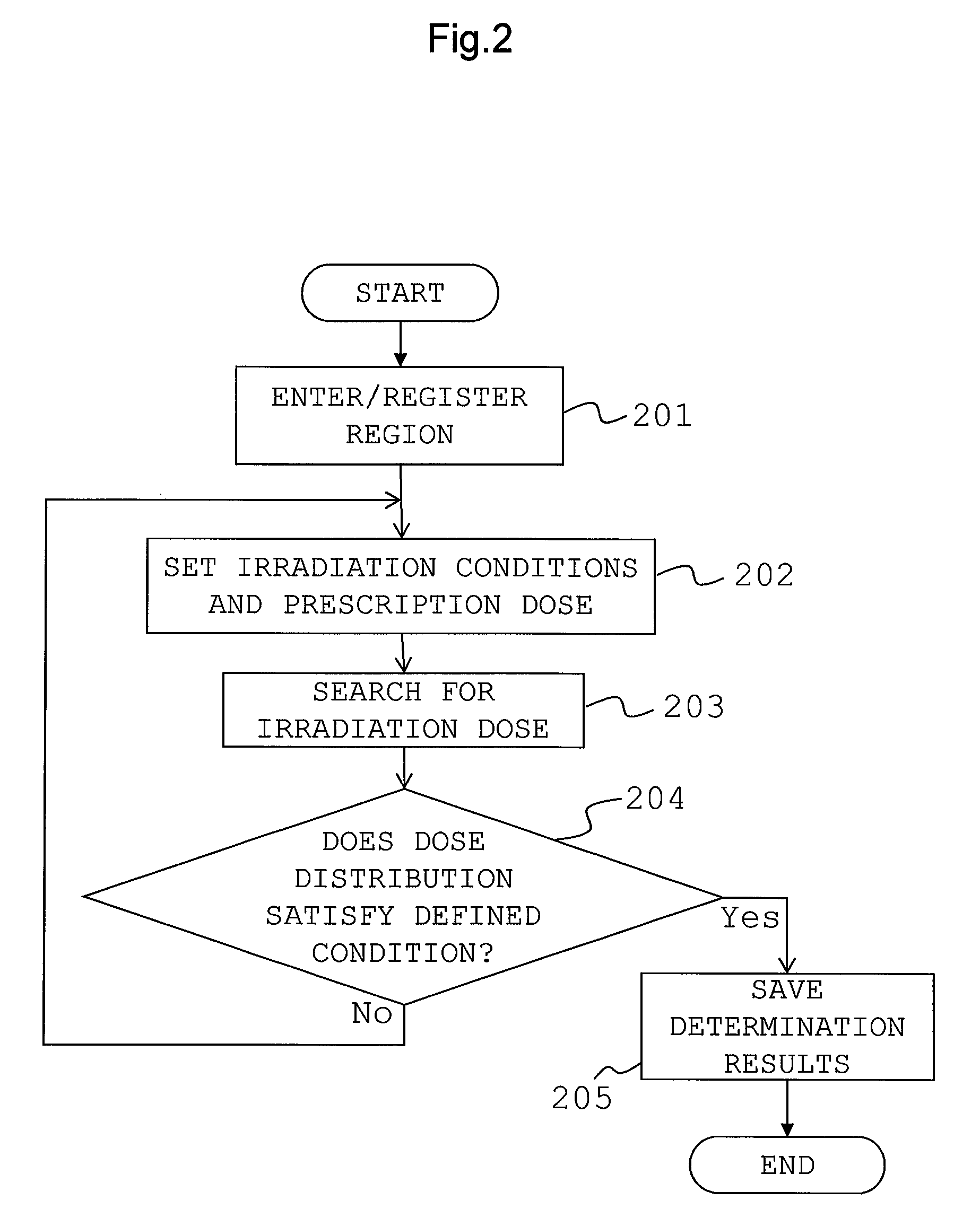
[0014]An object of the present invention is to provide a radiation treatment planning system that reduces a time needed to determine, by iterative calculation, optimal irradiation conditions based upon an operator-defined irradiating direction, prescription dose, and other conditions.
[0016]The present invention enables reduction in the time needed to determine the optimal irradiation conditions by the iterative calculation based upon the operator-defined irradiating direction, prescription dose, and other conditions.

Problems solved by technology

The increase in the beam size accordingly increases non-zero elements in the dose matrix used for the irradiation dose search, thus causes an increase in the load of iterative calculation and hence in a significant increase in calculation time.

Method used


Image

  • Radiation treatment planning system
  • Radiation treatment planning system
  • Radiation treatment planning system

Examples


Embodiment Construction

[0024]An embodiment of a radiation treatment planning system according to the present invention will be described hereunder using the accompanying drawings.

[0025]The embodiment of the radiation treatment planning system according to the present invention is described below using FIGS. 1 to 7.

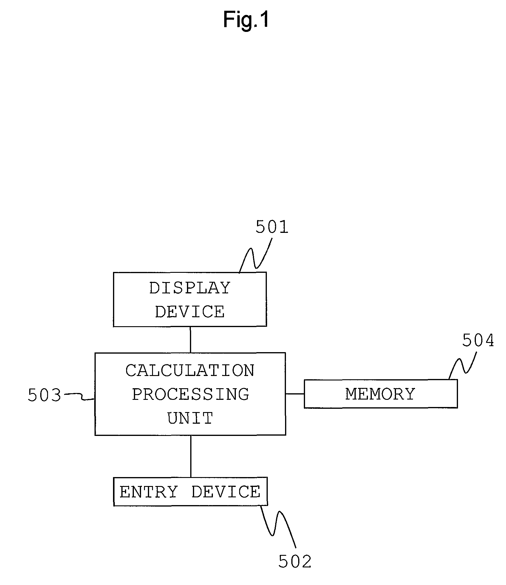
[0026]FIG. 1 is a diagram showing schematically a configuration of the radiation treatment planning system according to the embodiment of the present invention.

[0027]Referring to FIG. 1, the radiation treatment planning system according to the present embodiment schematically includes a display device 501, an entry device 502, an calculation processing unit 503, and a memory (storage device) 504.

[0028]The display device 501 has a region entry screen, on which CT images and other medical image information (tomographic image information) obtained by imaging a patient's target volume are displayed on a slice-by-slice basis. The image information is stored within, for example, the memory 504 of the ...


PUM


Abstract

Optimal irradiation conditions determined by iterative calculation are based upon an operator-defined irradiating direction, prescription dose, and other conditions. Dose matrixes A and B relating doses to calculation points from a beam delivered to irradiating positions are divided into a dose matrix AM or BM for the calculation points in a target region that are present at distances equal to or less than a distance L from the beam axis of the beam delivered to each spot, and a dose matrix AS or BS for the calculation points that are present at distances greater than L. When the iterative calculation is conducted following completion of the division, dose values and {right arrow over (d)}S(1) and {right arrow over (d)}S(2) that include the dose matrixes AS and BS are regarded as constants, and if updating conditions are satisfied, an objective function is recalculated using the values of the dose matrixes A, B and the spot irradiation dose {right arrow over (x)}.

Description

BACKGROUND OF THE INVENTION[0001]The present invention relates to a radiation treatment planning system.[0002]In radiation therapy, a treatment for target tumor cells is administered by irradiating the cells with radiation. While X-rays are most commonly used in radiation-based treatments, the therapy that uses charged particle beams represented by particle beams highly dose-convergent upon targets (i.e., proton beams and carbon beams) is increasing in demand.[0003]In radiation therapy, excess or deficiency of irradiation dose is likely to lead to side effects upon non-tumor normal tissues or to tumor recurrence. It is also demanded in particle therapy that a tumor region be irradiated with a dose that has been specified so that beam concentrates upon the tumor region as accurately as possible and as much as possible.[0004]The use of scanning in particle therapy is increasing as a method of concentrating a dose. The scanning method is intended to bend a thin beam of particles via tw...

Claims


Application Information

Patent Timeline
Patent Type & Authority Patents(United States)
IPC IPC(8): G21K5/00A61N5/01A61N5/06A61N5/10
CPCA61N5/01G21K5/00A61N2005/0635A61N2005/0627A61N2005/1072A61N5/1031
Inventor HIRAYAMA, SHUSUKEFUJIMOTO, RINTARONAGAMINE, YOSHIHIKO
Owner HITACHI LTD
Learn More