Paper detector with inducted module and printer using the same

a technology of inductance module and detector, which is applied in the direction of digitally marking record carriers, instruments, electromagnetic radiation sensing, etc., can solve the problems of increasing assembly difficulty and complex circuit layout, and achieves the effects of simplifying the product assembly process, reducing complex circuit design, and saving power

Inactive Publication Date: 2014-09-02
CAL COMP ELECTRONICS +1
View PDF13 Cites 0 Cited by
  • Summary
  • Abstract
  • Description
  • Claims
  • Application Information

AI Technical Summary

Benefits of technology

[0022]According to the above, the detector of the invention uses the principle of induced current induced by the inducted modules and the inducing unit for enabling the inducted modules to emit light. By applying the detector to the printer for detecting the paper barcode, it is able to reduce the complex circuit design in the printer of the related art, simplify the product assembly process, and achieve power-saving effect.

Problems solved by technology

Nevertheless, if the circuit of the light emitting unit 130 is designed in form of parallel, the circuit layout would be much intricate.
Moreover, a connection line or a connector is needed to electrically connect in between the circuit board 140 and the light emitting unit 130, thus increasing assembly difficulty.

Method used


Image

  • Paper detector with inducted module and printer using the same
  • Paper detector with inducted module and printer using the same
  • Paper detector with inducted module and printer using the same

Examples


Embodiment Construction

[0031]The following describes the components and the relative positions thereof for a detector of the invention with an exemplary embodiment of the detector in the application of a printer. The exemplary embodiment is only provided for illustration purpose, the application range of the detector is not limited thereto; one of ordinary skill in the art would be able to add or delete the components in combination of the detector in response to requirements, and to apply the detector in different machineries and equipments.

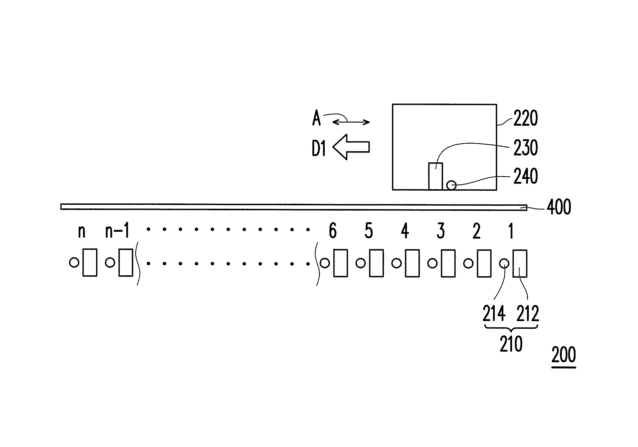
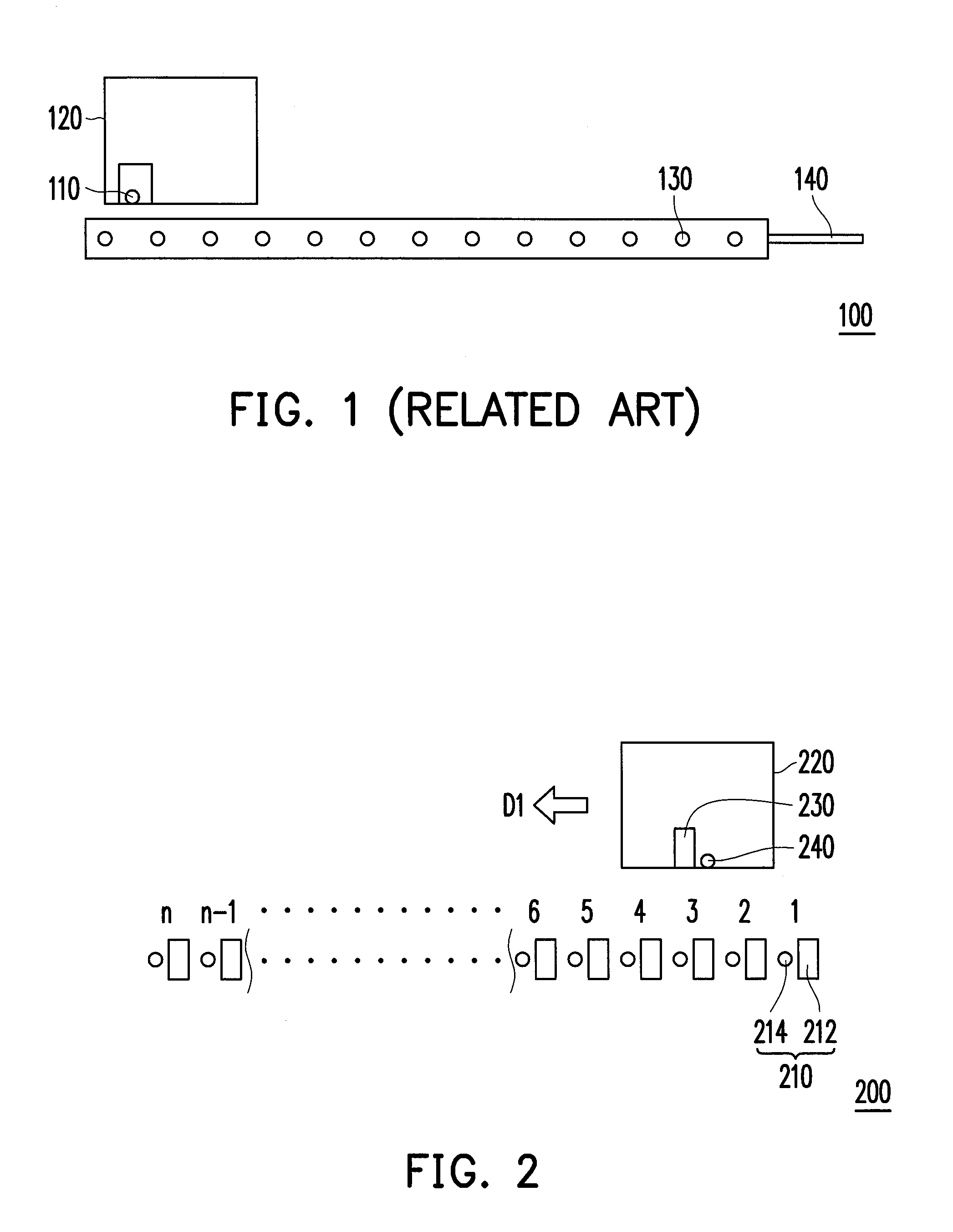
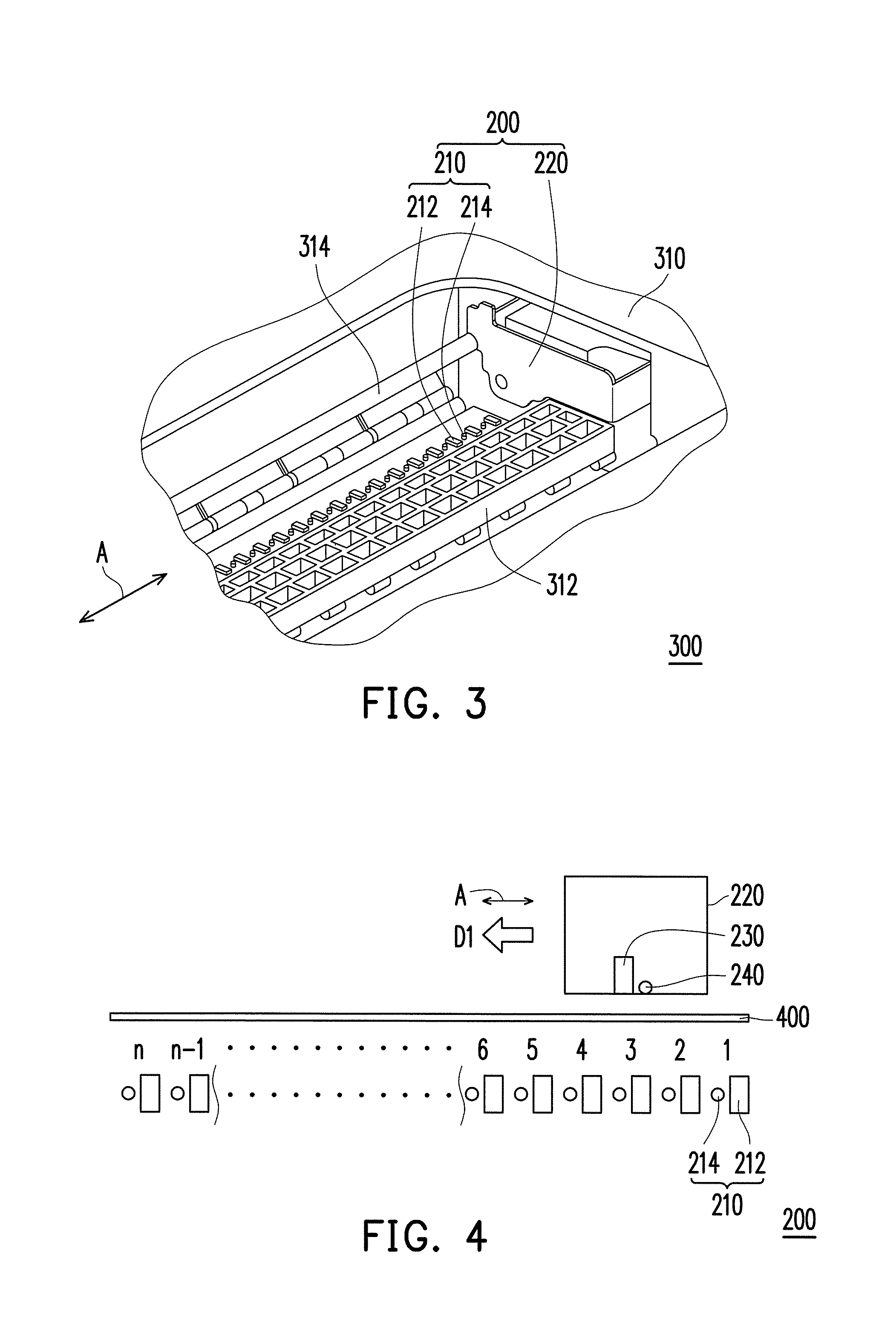
[0032]FIG. 2 is a schematic diagram illustrating a detector in accordance with an exemplary embodiment. With reference to FIG. 2, the detector 200 of the exemplary embodiment includes N inducted modules 210, a carriage 220, an inducing unit 230, and a light receiving unit 240, wherein N is a positive integer greater than or equal to 1, and the inducted modules 210 is aligned to a moving direction D1. The carriage 220 is disposed on the light emitting side of the induc...


PUM


Abstract

A detector and a printer using the same are provided. The printer includes a body and the detector. The body has a base and a shaft located above the base. The detector includes multiple inducted modules, a carriage, an inducing unit, and a light receiving unit. The inducted modules are disposed on the base of the body aligning to an axial direction of the shaft. The carriage is disposed on the shaft. The inducing unit and the light receiving unit are disposed on the carriage. During a printing process, the carriage moves back and forth along the axial direction, and the inducing unit induces the corresponding inducted modules to emit lights. The light receiving unit receives light emitted from one of the inducted modules and penetrated a paper undergoing the printing process for detecting a paper barcode.

Description

CROSS-REFERENCE TO RELATED APPLICATION[0001]This application claims the priority benefit of Taiwan application serial no. 101113481, filed on Apr. 16, 2012. The entirety of the above-mentioned patent application is hereby incorporated by reference herein and made a part of this specification.BACKGROUND[0002]1. Field of the Invention[0003]The invention relates to a detector and a printer, and more particularly to, a detector capable of achieving energy-saving-effect and a print using the same.[0004]2. Description of Related Art[0005]FIG. 1 is a schematic diagram illustrating a detector of a related art applied in a printer for detecting paper. Referring to the detector 100 of the related art in FIG. 1, a light receiving unit 110 is disposed on a carriage 120 that moves along a shaft (not shown), a plurality of light emitting units 130 is correspondingly disposed below the shaft (not shown) in a body (not shown) of a printer (not shown), and the light emitting units 130 are located on...

Claims


Application Information

Patent Timeline
Patent Type & Authority Patents(United States)
IPC IPC(8): H04N1/40G06K19/06
CPCB41J11/0095B41J11/009
Inventor TSAI, TING-SHI
Owner CAL COMP ELECTRONICS
Why Eureka
Try Eureka