Disk clamp having uniform clamping load and index mark

a technology of index mark and clamping load, which is applied in the field of disk clamps, can solve the problems of drive failure, transducer or disk failure, constant shrinkage of the structure of the system, etc., and achieve the effect of flatness and uniform circumferential clamp force of the disk clamp having balance weight holes and softening the area

Active Publication Date: 2014-09-02
INTRL PLEX TECH INC
View PDF23 Cites 2 Cited by
  • Summary
  • Abstract
  • Description
  • Claims
  • Application Information

AI Technical Summary

Benefits of technology

[0012]The flatness and uniform circumferential clamp force of a disk clamp having balance weight holes is substantially improved by using a coined index mark on the disk clamp instead of the extra reference holes. The variation in circumferential clamp force caused by the plurality of balance weight holes is reduced to a minimum by adding a formed or coined profile adjacent to or around the weight holes, thereby either stiffening the clamp at the area of each weight hole, or softening the area between the weight holes. The disk clamp contains a circular coined profile at the innermost section of the disk clamp which causes this innermost section to be in the plastic region of the stress-strain curve for the disk clamp, at the specified clamping force.

Problems solved by technology

The structural design of these systems is also continually shrinking, requiring hard disk drives having high capacity storage capability while occupying a minimal amount of space within the system.
This intermittent contact, if repeated, can damage the transducer or the disk and may cause drive failures.
Even very slight slippage of a disk within a drive could result in mechanical misalignment of the transducer which could result in data transfer errors or failure.
The positioning of the screws in the disk clamp causes the downward force to be exerted in a non-uniform manner.
Non-uniform clamping force causes variations in the load force and as a result, causes, at least the top mounted information storage disk to be physically distorted.
Distortion of the top disk even by as little as 40 microinches can lead to operational errors during recording and reproduction of data on the information storage disk.
This relative high torque leads to a number of problems, including over-stressing the spindle shaft bearing.
These high torque related problems can damage the bearing and lead to failure of the spindle motor.

Method used


Image

  • Disk clamp having uniform clamping load and index mark
  • Disk clamp having uniform clamping load and index mark
  • Disk clamp having uniform clamping load and index mark

Examples


Embodiment Construction

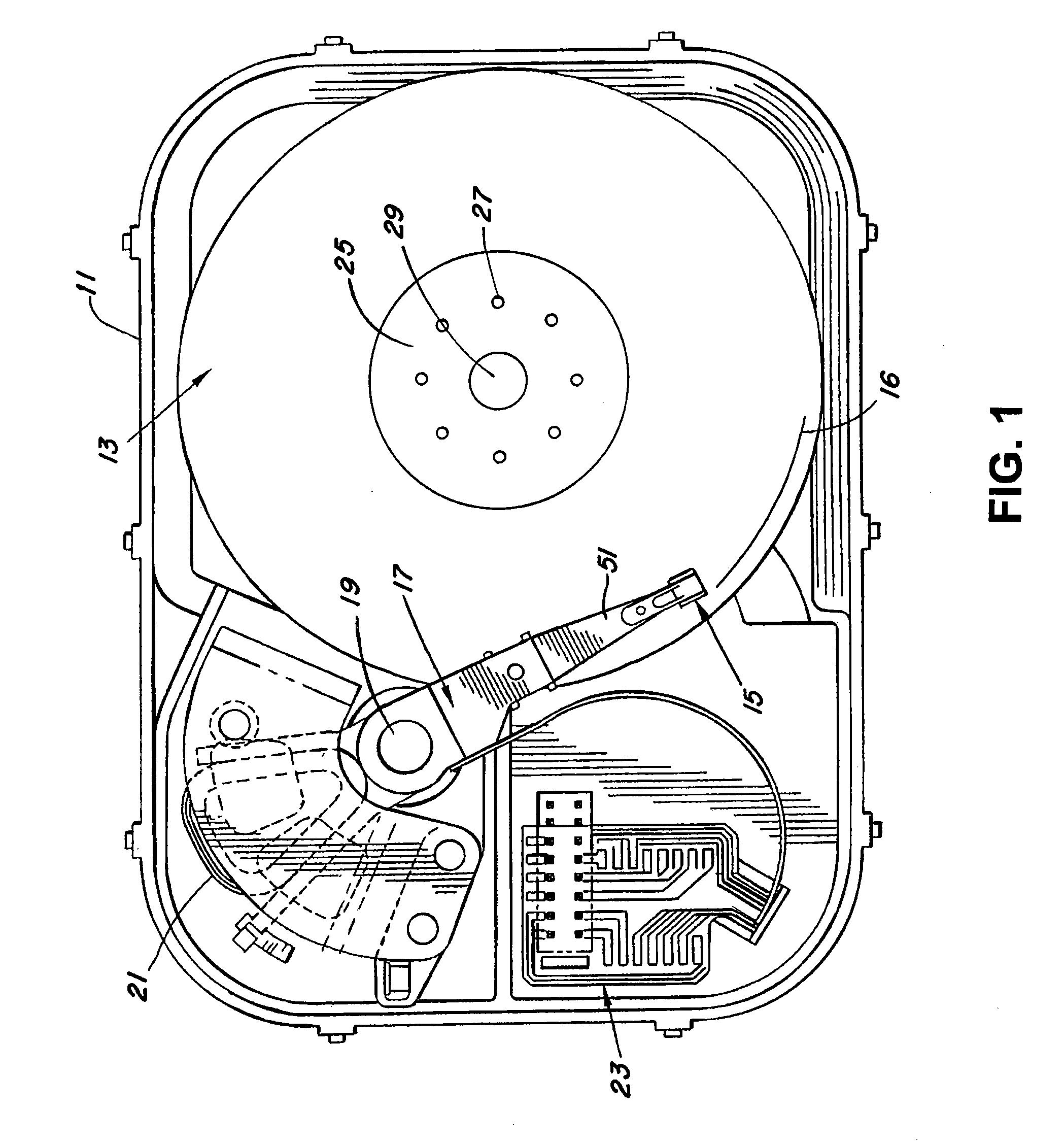
[0034]FIG. 1 represents a cut-away top view of a disk drive 11 having one or more hard disks 13 with each of the hard disks having information written in a series of data tracks 16 thereon. The disk drive 11 utilizes at least one transducer 15 for reading and writing information to the hard disk 13. The transducer 15 may be a conventional conductive element or a magneto-resistive element, for example. The transducer 15 is connected to an actuator arm 17. The movements of the actuator arm 17 are controlled by a voice coil motor 21 causing the arm to pivot about a pivot junction 19. A control circuit 23 is used to control the operation of the actuator arm 17 and other components (not shown) within the disk drive 11.

[0035]During a seek operation, for example, the track position of the head 15 is moved across the surface of the disk 13. The head 15 is connected to the actuator arm 17 by a flexure 51.

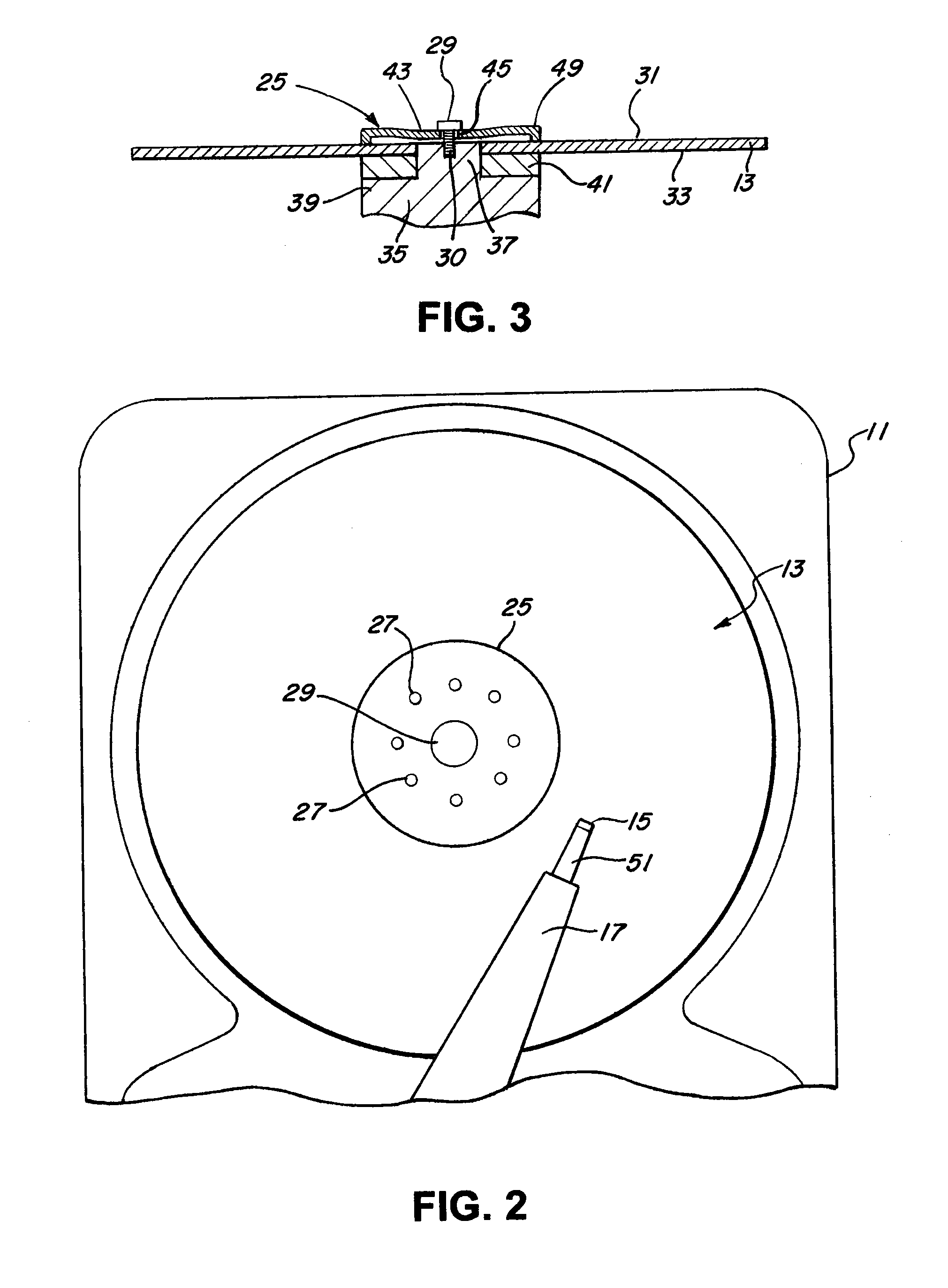
[0036]The hard disk 13 may be a single disk or a stack of disks. The hard disk 13 is con...


PUM

PropertyMeasurementUnit
thicknessaaaaaaaaaa
thicknessaaaaaaaaaa
outer diameteraaaaaaaaaa

Abstract

A disk clamp for clamping a number of magnetic hard disks within a disk drive has a plurality of balance weight holes and a coined index mark for use as a reference in balancing the hard disks after assembly. The disk clamp also has a coined profile located adjacent or around the balance weight holes in order to provide uniform circumferential clamp force by the disk clamp. The disk clamp has a profile that places the inner region of the disk clamp in the plastic deformation region at a certain specified clamping force at the center of the disk clamp.

Description

BACKGROUND OF THE INVENTION[0001]1. Field of the Invention[0002]The present invention relates to disk drives and more specifically, to a disk clamp for a disk drive that provides a uniform clamping load.[0003]2. Description of Related Art[0004]Work stations, personal computers and laptop computers require disk drives that provide a large amount of data storage within a minimal physical area. A disk drive typically includes one or more hard disks that are rotated at a constant high speed by a spindle motor. Generally, disk drives operate by positioning a transducer or read / write head over respective tracks on the disks. The information is written to and read from tracks on the disks through the use of an actuator assembly which rotates during a seek operation. The actuator is coupled to control electronics which control the positioning of the actuator and the read / write functions of the transducer. A typical actuator assembly includes a plurality of actuator arms which extend towards...

Claims


Application Information

Patent Timeline
Patent Type & Authority Patents(United States)
IPC IPC(8): G11B17/22G11B17/022
CPCG11B17/0287
Inventor PETERSEN, FREDERIC C.SCHMIDT, RYAN J.SMITH, PAUL W.SUTTON, ADAM D.
Owner INTRL PLEX TECH INC
Why Eureka
Try Eureka