
Image forming method

a technology of image forming and transfer belt, which is applied in the direction of electrographic process, instruments, synthetic resin layered products, etc., can solve the problems of shortened lifespan of intermediate transfer belt, deterioration of electric properties with repeated image forming operations, and easy insertion of transfer belts

Active Publication Date: 2014-09-09
RICOH KK
View PDF16 Cites 1 Cited by
  • Summary
  • Abstract
  • Description
  • Claims
  • Application Information

AI Technical Summary

Benefits of technology

The present invention provides a method for forming high-quality images that do not have any image defects, density unevenness, or color unevenness for a long time, even when the image forming speed is high.

Problems solved by technology

In operation, such intermediate transfer belts are susceptible to two phenomena, abrasion and filming.
However, the electric properties deteriorate with repeated image forming operations, because the cleaning blade is constantly pressed against the intermediate transfer belt.
Thus, the lifespan of the intermediate transfer belt is shortened and eventually abnormal images are produced.
The electric properties of the intermediate transfer belt deteriorate due to the occurrence of filming.
Such loading materials are likely to adhere to the intermediate transfer belt when images are transferred from the intermediate transfer belt onto such types of paper, and the adhered loading materials are likely to cause filming.
However, when the printing speed is high, as is consistent with recent demand, abnormal images with undesired stripes may be formed in continuous image forming operations.
Thus, the electric properties of the portion to which toner component materials and loading materials are adhered deteriorate, resulting in production of abnormal images with undesired strips.
However, even in a case where a sufficient amount of a metal soap was adhered to the intermediate transfer belt, filming occurred in some portions on the intermediate transfer belt when images were formed at high speeds.
Accordingly, to form high quality images even when the printing speed is high, the metal soap is required to be applied to the whole surface of the intermediate transfer belt, which has never been achieved.
However, the theoretical saturation amount of zinc, i.e., 2.44% by atom, which is theoretically calculated from the elemental composition of zinc stearate, cannot be used for calculation of the coverage of the mixture of zinc stearate and zinc palmitate.
The theoretical saturation amount of zinc has to be recalculated for each mixing ratio of zinc stearate and zinc palmitate, which is less practical and economical, and more cumbersome.
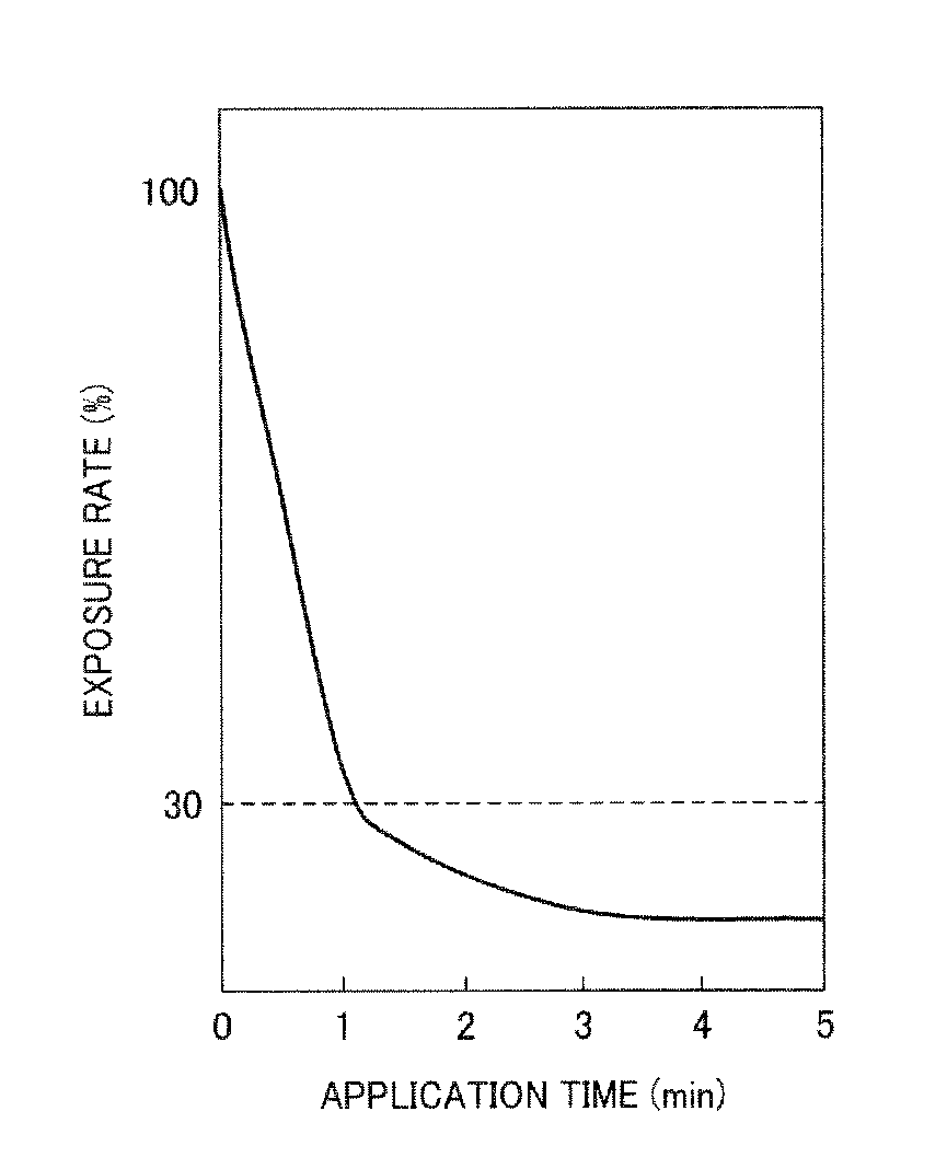
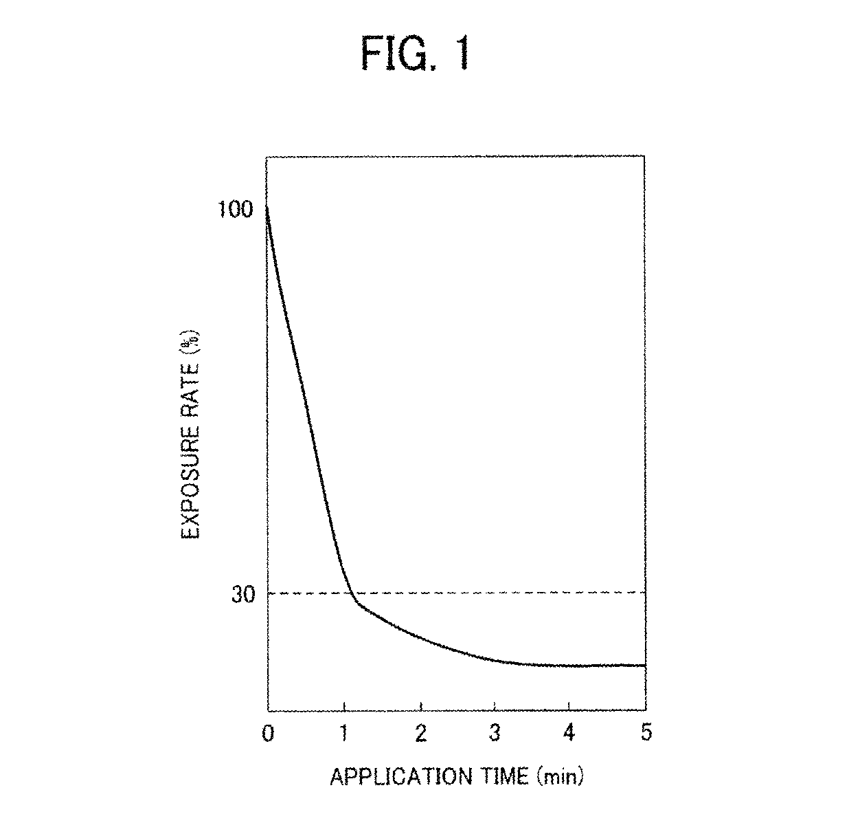
However, even when the exposure rate thus calculated before any given image forming operation is 30% or less, blurred images are found to be produced under high-temperature and high-humidity conditions in some cases.

Method used


Image

  • Image forming method
  • Image forming method
  • Image forming method

Examples


example 1

(Preparation of Intermediate Transfer Belt A)

[0166]To prepare a carbon black dispersion, 2 parts of a polyimide solution U-Varnish A (including 18% of solid components, from Ube Industries, Ltd.), 8 parts of a carbon black Special Black 4A (from Degussa), and 90 parts of N-methyl-2-pyrrolidone (from Mitsubishi Chemical Corporation) are mixed, and the mixture is subjected to a dispersion treatment for 5 hours using a bead mill disperser filled with zirconia beads with a diameter of 1 mm.

[0167]To prepare a coating liquid, 50 parts of the above-prepared carbon black dispersion, 50 parts of a polyimide solution U-Varnish A (including 18% of solid components, from Ube Industries, Ltd.), and 0.01 parts of a polyether-modified silicone FZ2105 (from Dow Corning Toray Co., Ltd.) are mixed, and the mixture is subjected to defoaming using a centrifugal agitation defoaming device.

[0168]The coating liquid is poured into a metallic cylindrical mold having an outer diameter of 100 mm and a length ...

example 2

(Preparation of Intermediate Transfer Belt B)

[0174]The procedure for preparation of the intermediate transfer belt A in Example 1 is repeated except for changing the profile of the convexities on the surface. Specifically, the mold is changed to another mold, the inner surface of which has linear concavities with a depth of 0.02 μm and a width of 1 μm, which are formed so that the average area defined by the linear concavities is 3,000 μm2.

[0175]Thus, an intermediate transfer belt B is prepared. The surface of the intermediate transfer belt B has linear convexities with a height of 0.02 μm and a width of 1 μm. The average area defined by the linear convexities is 3,000 μm2.

(Evaluation)

[0176]The intermediate transfer belt B is evaluated as the same manner in Example 1.

example 3

(Preparation of Intermediate Transfer Belt C)

[0177]The procedure for preparation of the intermediate transfer belt A in Example 1 is repeated except for changing the profile of the convexities on the surface. Specifically, the mold is changed to another mold, the inner surface of which has linear concavities with a depth of 0.1 μm and a width of 1 μm, which are formed so that an area defined by the linear concavities is 3,000 μm2.

[0178]Thus, an intermediate transfer belt C is prepared. The surface of the intermediate transfer belt C has linear convexities with a height of 0.1 μm and a width of 1 μm. The average area defined by the linear convexities is 3,000 μm2.

(Evaluation)

[0179]The intermediate transfer belt C is evaluated as the same manner in Example 1.


PUM

PropertyMeasurementUnit
areaaaaaaaaaaa
widthaaaaaaaaaa
heightaaaaaaaaaa

Abstract

An image forming method which applies a zinc-containing metal soap to a surface of an intermediate transfer belt including nitrogen on its surface. At least one of the following formulae is satisfied:(1−C / D)×100(%)−(B / A)×100(%)≦10(%)(F / E)×100(%)≦30(%)wherein A and B represent a percentage content of nitrogen at the surface of the intermediate transfer belt before and after image formation on 1,000 sheets, respectively, C represents a percentage content of zinc at the surface of the intermediate transfer belt after the image formation on 1,000 sheets, D represents a percentage content of zinc based on all elements other than hydrogen in the zinc-containing metal soap, and E and F represent a percentage content of nitrogen at the surface of the intermediate transfer belt before and after application of the metal soap thereto for 5 minutes without image formation, respectively.

Description

CROSS-REFERENCE TO RELATED APPLICATIONS[0001]The present patent application claims priority pursuant to 35 U.S.C. §119 from Japanese Patent Application Nos. 2009-195225 and 2009-251896, filed on Aug. 26, 2009 and Nov. 2, 2009, respectively, each of which is hereby incorporated by reference herein in its entirety.BACKGROUND[0002]1. Field of the Invention[0003]The present invention relates to an electrophotographic image forming method.[0004]2. Description of the Background[0005]In electrophotographic image forming apparatuses, seamless belts are used with various functions and uses, such as a paper conveyance belt.[0006]Recently, seamless belts are also used as an intermediate transfer belt in full-color electrophotographic image forming apparatuses. The intermediate transfer belt is a member onto which four or more toner images of different colors are transferred from one or more photoreceptors to form a composite full-color toner image thereon. The composite full-color toner image ...

Claims


Application Information

Patent Timeline
Patent Type & Authority Patents(United States)
IPC IPC(8): B32B27/00G03G15/16
CPCG03G15/1605Y10T428/31855
Inventor SHIONOIRI, MOMOKOKABATA, TOSHIYUKI
Owner RICOH KK
Learn More