Method and system for determining poses of vehicle-mounted cameras for in-road obstacle detection

a vehicle-mounted camera and obstacle detection technology, applied in image analysis, image enhancement, details involving processing steps, etc., can solve problems such as high computational complexity of slam-based methods, inability to meet real-time applications, and inability to use real-time applications

Active Publication Date: 2014-09-09
MITSUBISHI ELECTRIC RES LAB INC
View PDF0 Cites 14 Cited by
  • Summary
  • Abstract
  • Description
  • Claims
  • Application Information

AI Technical Summary

Benefits of technology

[0021]Using this hybrid approach, accurate motion estimates can be generated for a plane-sweeping procedure that produces dense depth-maps for obstacle detection applications.

Problems solved by technology

Accurate motion estimation of an object, such as a vehicle or robot, from a video acquired of an environment, e.g., a road or garage, near the vehicle by a camera mounted on the vehicle is an important problem in vehicle and robot navigation.
Given the complexity of the equations, that method determines the solutions iteratively with a Newton-Raphson algorithm, which consumes time, and not amenable for real-time applications.
However, SLAM-based methods suffer high computational complexity because properly treating the correlations is computationally complex, and thus performing vision-based SLAM in environments with thousands of features is problematic for real-time applications.

Method used


Image

  • Method and system for determining poses of vehicle-mounted cameras for in-road obstacle detection
  • Method and system for determining poses of vehicle-mounted cameras for in-road obstacle detection
  • Method and system for determining poses of vehicle-mounted cameras for in-road obstacle detection

Examples


Embodiment Construction

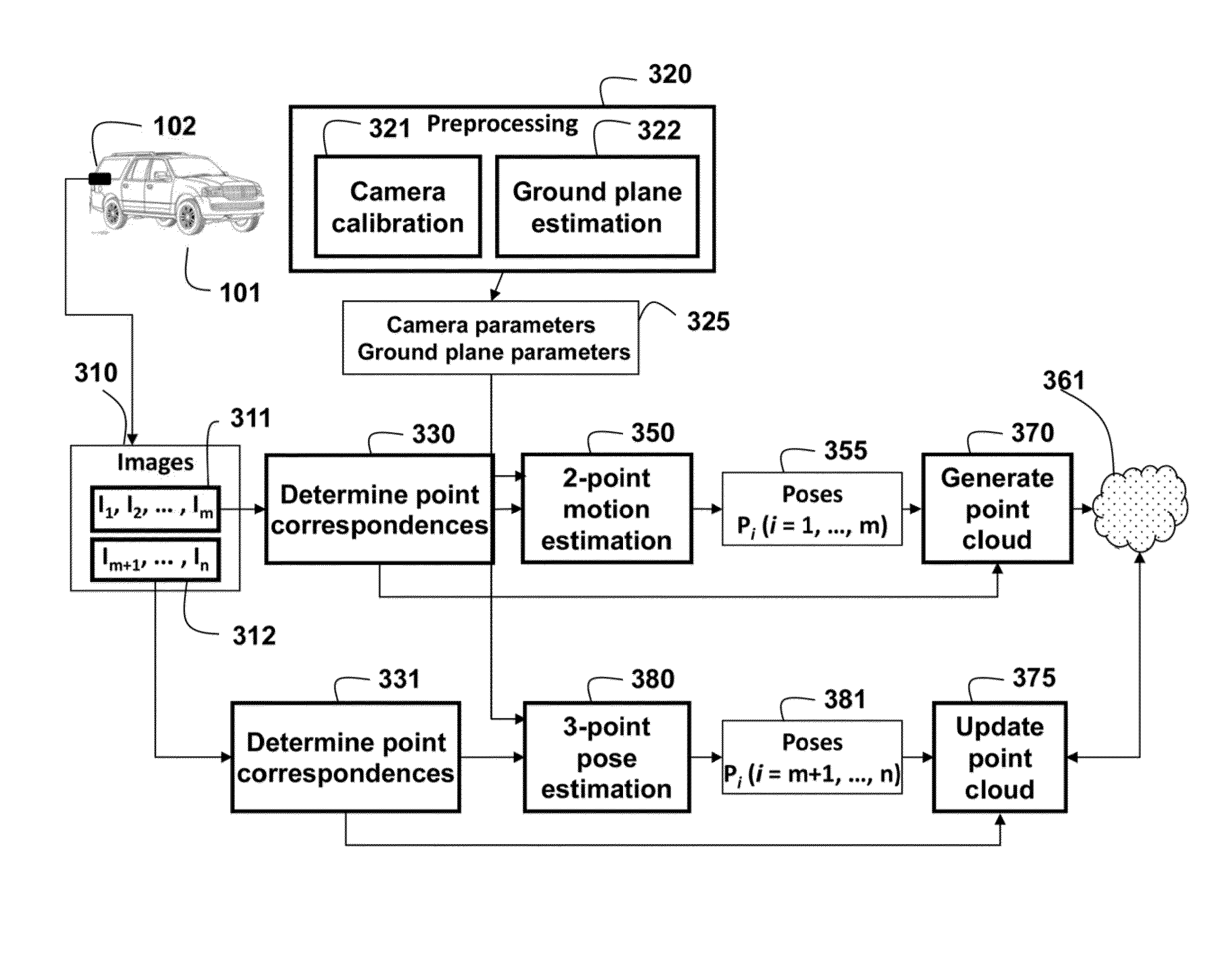
[0026]The embodiments of the invention provide a method for determining poses of a camera from a sequence of images in a video acquired of an environment 103 near a movable object by the camera mounted on the object. The object can be a car, truck, bicycle, taxiing plane, robot, person, etc. Because the camera is in a fixed relationship with respect of the object, the pose of the camera can be used to determine the pose of the object, the motion of the object, as well as potential obstacles near the object.

[0027]As generally defined herein, a pose includes a location and orientation of the camera: The translational location T and angular orientation R each can have up to three degrees of freedom.

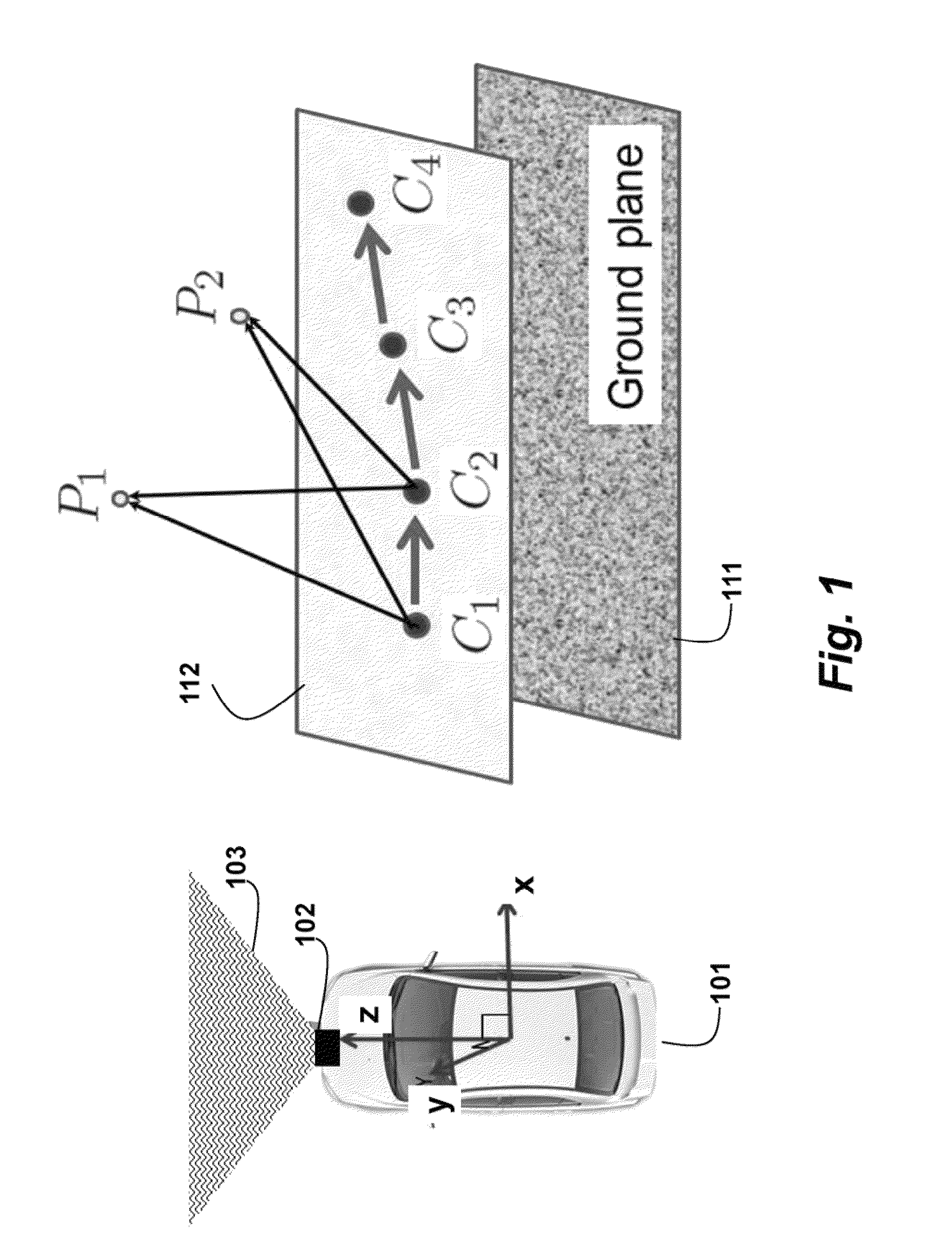
[0028]Motion Estimation

[0029]FIG. 1 shows two-point motion estimation for planar motion of a vehicle 101. The motion of the vehicle is substantially coplanar to a ground plane 111. The camera 102 moves on a plane 112 parallel to the ground plane along coordinate systems C1, C2, C3, C4. The f...


PUM


Abstract

Poses of a movable camera relative to an environment are obtained by determining point correspondences from a set of initial images and then applying 2-point motion estimation to the point correspondences to determine a set of initial poses of the camera. A point cloud is generated from the set of initial poses and the point correspondences. Then, for each next image, the point correspondences and corresponding poses are determined, while updating the point cloud.

Description

FIELD OF THE INVENTION[0001]This invention relates generally to using computer vision for motion estimation, and more particularly to using the motion estimation for pose determinations of vehicle-mounted cameras to detect obstacles near vehicles.BACKGROUND OF THE INVENTION[0002]Accurate motion estimation of an object, such as a vehicle or robot, from a video acquired of an environment, e.g., a road or garage, near the vehicle by a camera mounted on the vehicle is an important problem in vehicle and robot navigation. Most conventional methods either use a camera model (monocular or stereo), or a motion model (planar or non-planar). To determine a relative motion of the vehicle with respect to the environment from a sequence of images, a minimal number of feature correspondences in a hypothesize-and-test framework, such as random sample consensus (RANSAC), produces accurate results in the presence of outliers.[0003]Dense depth estimation from video sequences using a vehicle-mounted c...

Claims


Application Information

Patent Timeline
Patent Type & Authority Patents(United States)
IPC IPC(8): G06T7/20
CPCG06T7/0071G06T7/0042G06T2200/08G06T2207/10016G06T2207/20076G06T2207/30244G06T2207/30261G06T7/73G06T7/579
Inventor RAMALINGAM, SRIKUMARTAGUCHI, YUICHIZHU, MENGLONG
Owner MITSUBISHI ELECTRIC RES LAB INC
Why Eureka
Try Eureka