
Control device for hybrid construction machine

a control device and construction machine technology, applied in the direction of fluid couplings, servomotors, couplings, etc., can solve the problems of large energy loss, engine consume energy despite substantially no work, etc., and achieve the effect of suppressing energy loss

Inactive Publication Date: 2014-09-16
KYB CORP
View PDF9 Cites 6 Cited by
  • Summary
  • Abstract
  • Description
  • Claims
  • Application Information

AI Technical Summary

Benefits of technology

The invention allows for the actuator to use the hydraulic motor to generate power when it is in a non-operative condition. This reduces energy loss and ensures that the actuator can function efficiently.

Problems solved by technology

Therefore, when the actuators are inoperative, the engine consumes energy despite doing substantially no work.
As a result, great energy loss occurs.

Method used


Image

  • Control device for hybrid construction machine
  • Control device for hybrid construction machine
  • Control device for hybrid construction machine

Examples


Embodiment Construction

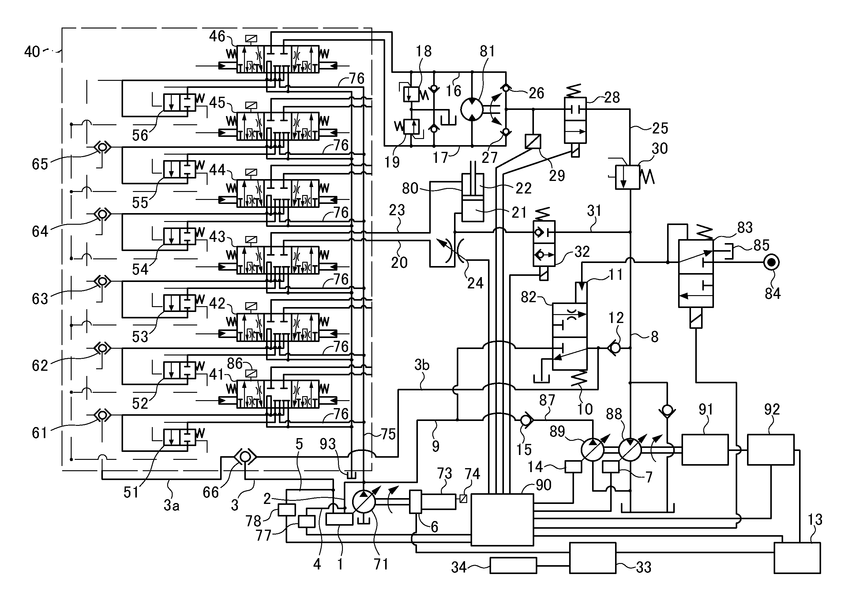
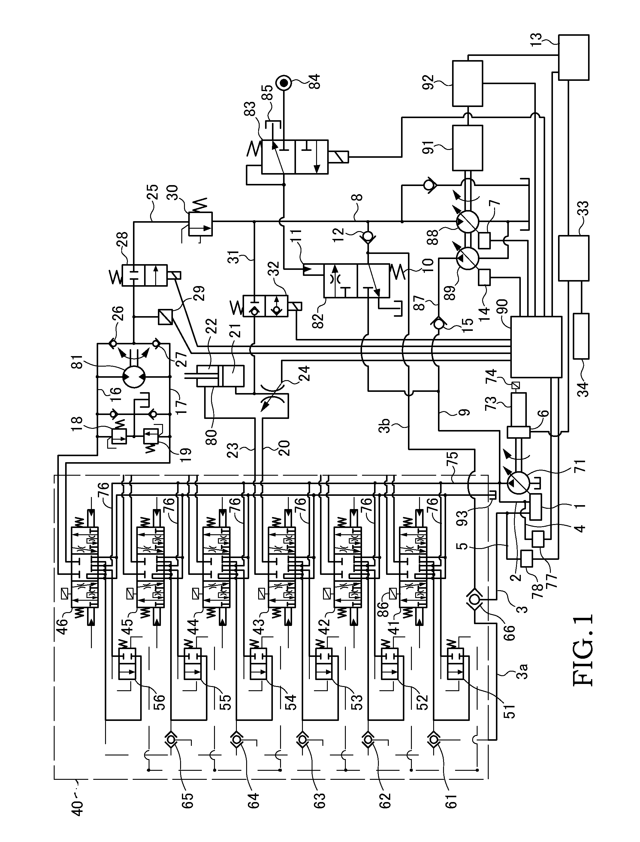
[0012]A control device for a hybrid construction machine according to an embodiment of this invention will be described below with reference to the figures. In the following embodiment, a case in which the hybrid construction machine is a power shovel will be described.

[0013]As shown in FIG. 1, the power shovel is provided with a variable volume type main pump 71 that rotates using a driving force of an engine 73 serving as a prime mover. The engine 73 is provided with a generator 6 that exhibits a power generation function using a surplus force of the engine 73. The engine 73 is also provided with a rotation speed sensor 74 serving as a rotation speed detector that detects a rotation speed of the engine 73. A main flow passage 75 through which a discharged working oil passes is connected to the main pump 71.

[0014]The power shovel includes a load sensing circuit 40. The load sensing circuit 40 is provided with operation valves 41, 42 that control a travel motor, an operation valve 4...


PUM


Abstract

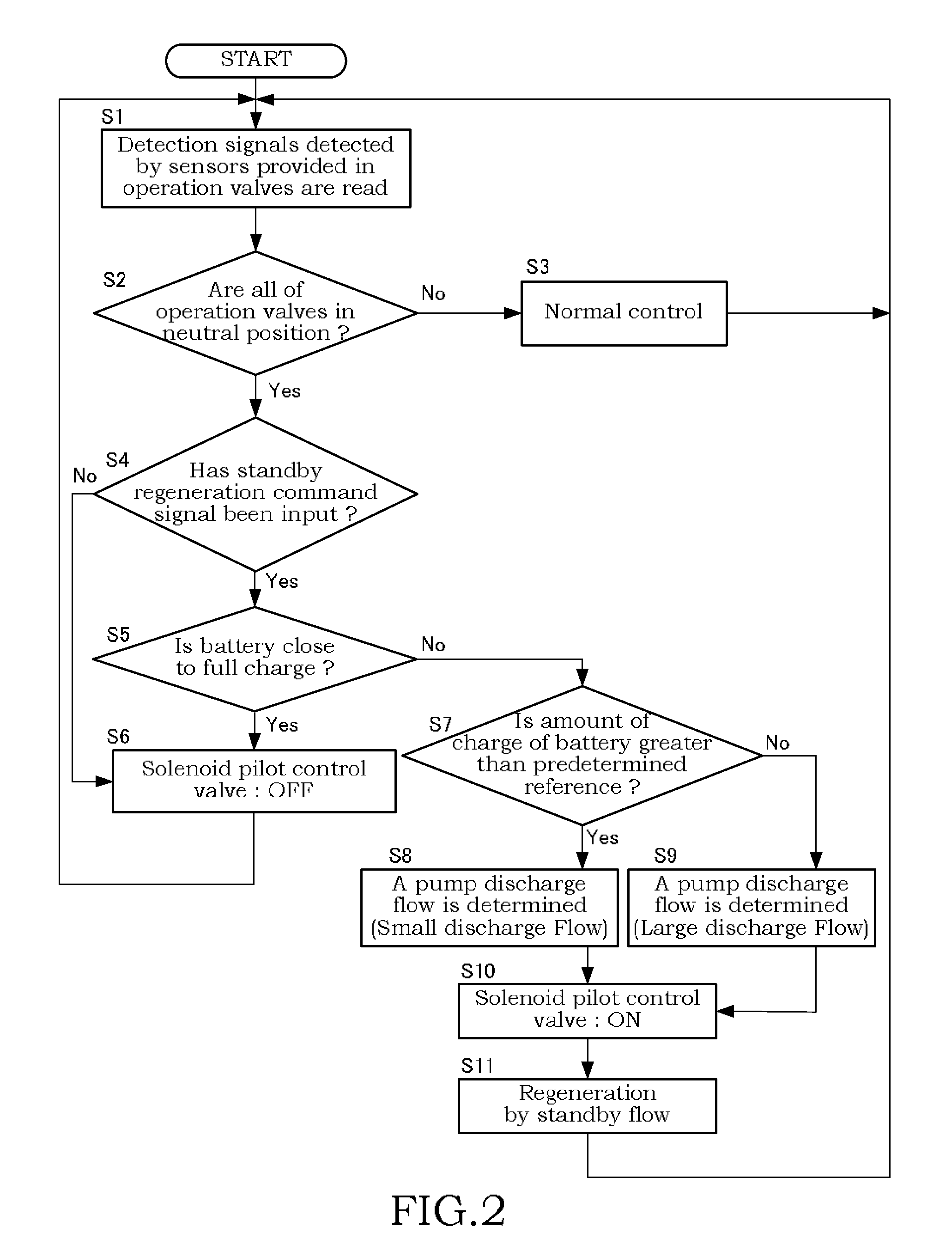
A control device for a hybrid construction machine includes a discharge pressure introduction passage that leads a discharge pressure from a variable volume pump to a regulator, and a load pressure introduction passage that leads one of a maximum load pressure of respective actuators and a load pressure of a hydraulic motor to the regulator. A controller, having determined that the actuators are in an inoperative condition on the basis of a detection result from an operating condition detector, excites a solenoid of a solenoid pilot control valve such that a discharge oil from the variable volume pump is led to the hydraulic motor, and controls the regulator such that a differential pressure between the discharge pressure of the variable volume pump and the load pressure of the hydraulic motor is kept constant.

Description

TECHNICAL FIELD[0001]This invention relates to a control device for a hybrid construction machine that uses an electric motor as a drive source.BACKGROUND ART[0002]In a known conventional control device including a load sensing circuit, a maximum load pressure of a plurality of actuators connected to a circuit system is selected, whereupon a regulator controls a discharge flow of a main pump such that a differential pressure between the selected maximum load pressure and a discharge pressure of the main pump remains constant. Further, an operation valve and a pressure compensation valve are connected to each actuator, and control is performed such that a supply flow remains constant regardless of variation in the load pressure of the actuators (see JP2004-197825A).SUMMARY OF THE INVENTION[0003]In the conventional device described above, an engine rotates constantly, even when the respective actuators are in an inoperative condition. Therefore, when the actuators are inoperative, the...

Claims


Application Information

Patent Timeline
Patent Type & Authority Patents(United States)
IPC IPC(8): F16D31/02E02F9/20E02F9/22F15B21/14
CPCE02F9/2235E02F9/2296F15B21/14E02F9/2075E02F9/2292F15B2211/30555F15B2211/20546F15B2211/88F15B2211/20515F15B2211/265F15B2211/20523F15B2211/20576E02F9/22F15B13/043F16K31/04
Inventor KAWASAKI, HARUHIKOEGAWA, MASAHIRO
Owner KYB CORP
Learn More