
Warning light frame with integral screw anchors

a technology of warning lights and screws, which is applied in the direction of lighting support devices, lighting and heating apparatus, and ways. it can solve the problems of preventing the proper insertion of fasteners, affecting the safety of drivers, so as to achieve simple and reliable installation and removal of fasteners.

Active Publication Date: 2014-09-16
WHELEN ENGINEERING COMPANY
View PDF19 Cites 4 Cited by
  • Summary
  • Abstract
  • Description
  • Claims
  • Application Information

AI Technical Summary

Benefits of technology

The invention is a warning light assembly for mounting on motor vehicles that includes a frame and retention legs. The frame has fastener receptacles with retaining legs that secure the assembly to the vehicle. The retention legs have ribs or ridges that catch on the inside of the vehicle's hole and secure the assembly. The flexible material of the frame and retention legs allows them to flex inwardly during insertion and outwardly when pressure is applied. The fasteners secure the frame to the vehicle's exterior surface and provide a secure and reliable attachment. The assembly is easy to install and remove. The technical effects of the invention include simplified assembly and installation of warning lights, secure attachment to the vehicle, and reliable fastener installation and removal.

Problems solved by technology

Typically, a vehicle to which warning lights are to be mounted has already been constructed, so access to the rear side of the sheet material forming the exterior of the motor vehicle is obstructed.
Screw grommets used in round holes can be problematic in that the engagement between the outside surface of the screw grommet and the round hole is relatively light, meaning that relatively little rotational force applied to the screw grommet can cause rotation of the screw grommet relative to the work piece and prevent proper insertion of a fastener through the screw grommet.
A common problem with individual screw grommets is that the screw grommet will rotate behind the warning light, preventing advancement of fasteners through the screw grommet to secure the light to the vehicle.
Once a screw grommet begins rotating behind a partially installed warning light, removal of the fastener and warning light is problematic.
Sheet metal fasteners have a tendency to strip, preventing secure attachment of the warning light to the vehicle.
Further, sheet metal fasteners have the potential to exert excessive force on the warning light, resulting in bent or cracked warning light housings.

Method used


Image

  • Warning light frame with integral screw anchors
  • Warning light frame with integral screw anchors
  • Warning light frame with integral screw anchors

Examples


Embodiment Construction

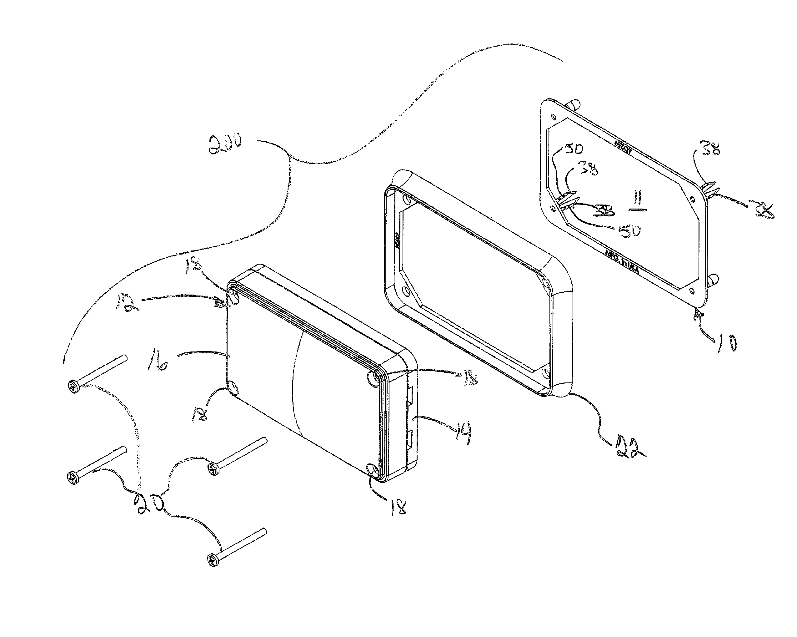
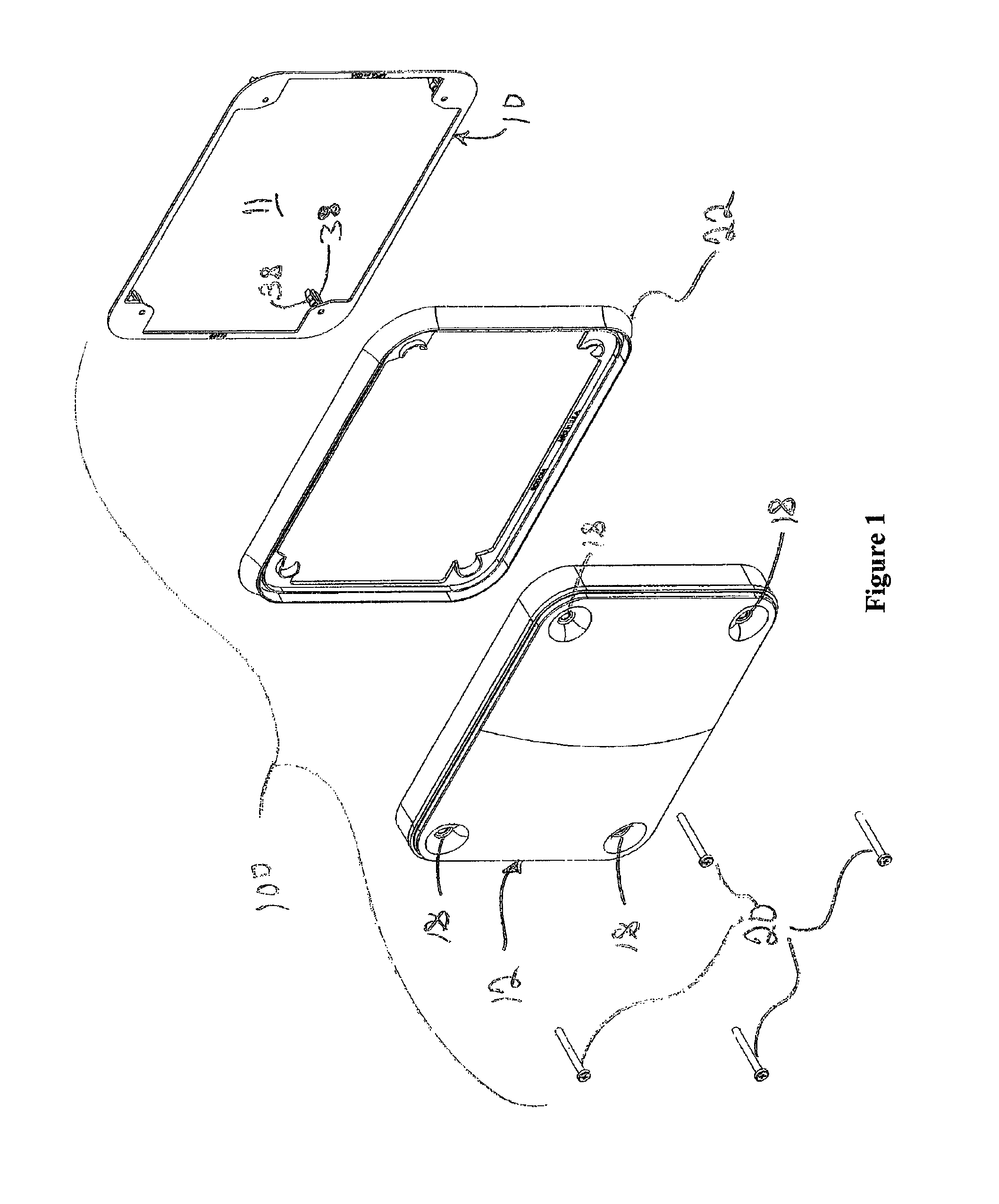
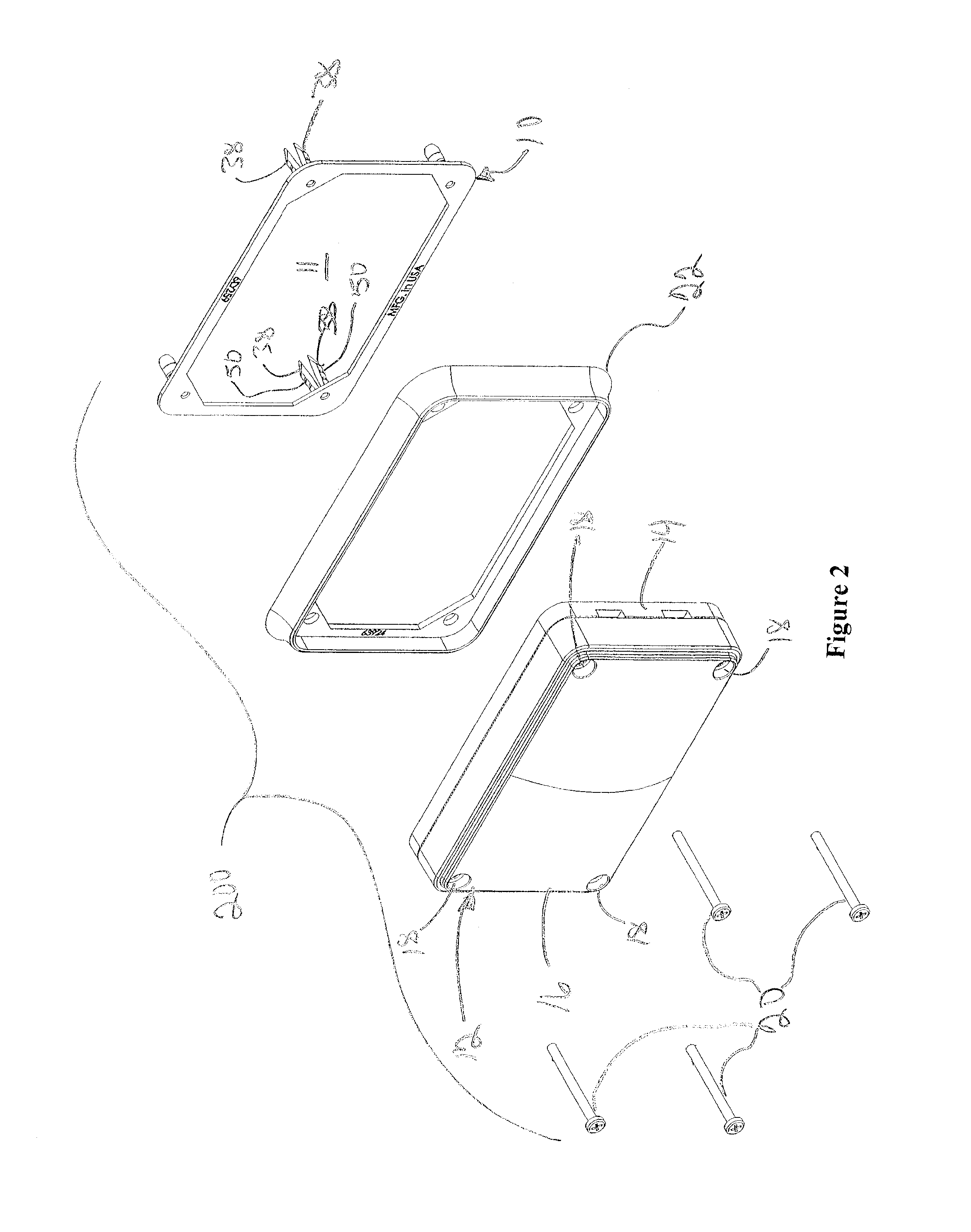
[0014]FIGS. 1 and 2 illustrate warning light assemblies 100, 200 designed to be mounted on the exterior surfaces of motor vehicles (not shown) such as fire trucks, rescue vehicles and ambulances. The disclosed warning light assemblies 100, 200 are typically mounted to vertical surfaces on the front, sides, and rear of emergency vehicles. Emergency vehicles are commonly trucks or vans with vehicle bodies constructed of sheet materials such as steel, plastic, or fiber glass. Warning lights are installed after the vehicle is substantially complete and it is common for the installer to have access only to the outside surface of the sheet material forming the vehicle body. Such an installation may be referred to as a “blind” installation. This means that any mounting system must be capable of installation from the outside of the vehicle and cannot require access to the rear surface of the vehicle panel.

[0015]The illustrated warning light assemblies 100, 200 include a warning light having...


PUM


Abstract

A warning light assembly includes a frame with integral fastener anchors. The frame aligns and supports the anchors with openings in a vehicle body or other support surface. Fasteners pass through a warning light housing to spread retention legs behind the support surface. The anchors are connected by the frame and cannot rotate relative to the vehicle body or warning light. The frame defines a central opening for warning lights requiring additional depth.

Description

FIELD OF THE INVENTION[0001]The present disclosure relates to apparatus and methods for mounting warning lights to the exterior of motor vehicles used for emergency response such as police, rescue, fire, and ambulance vehicles.BACKGROUND OF THE INVENTION[0002]Emergency vehicles require warning lights arranged about the exterior to emit warning light signals in patterns specified by various federal and state regulations as well as standards set by industry organizations. Standards relevant to this disclosure include: the Federal KKK Standard for ambulance lighting, the Society of Automotive Engineers (SAE) Surface Vehicle Recommended Practice standards including SAEJ595, J1849, J759, J845, National Fire Protection Association (NFPA) standard 1901, and California Code of Regulations Title 13. The standards set forth in these documents include specifications for exterior warning lighting for emergency vehicles. To meet these requirements, it is frequently necessary to mount warning lig...

Claims


Application Information

Patent Timeline
Patent Type & Authority Patents(United States)
IPC IPC(8): B60Q1/26F21V21/00B60Q1/00F21V9/00
CPCF21V9/00B60Q1/26F21V21/00B60Q1/00B60Q1/263B60Q1/2615
Inventor LYONS, JON, H.
Owner WHELEN ENGINEERING COMPANY
Learn More