Belt type continuously variable transmission

a technology of continuously variable transmission and belt type, which is applied in the direction of gearing details, belt/chain/gearing, gear lubrication/cooling, etc., can solve the problems of difficult to form a flow of cooling air directed from the drive pulley toward the driven pulley, and the interference of the driven pulley with the other pulley in a complex manner, so as to suppress the interference of the flow and improve the overall cooling efficiency

Active Publication Date: 2014-09-16
KAWASAKI MOTORS LTD
View PDF28 Cites 29 Cited by
  • Summary
  • Abstract
  • Description
  • Claims
  • Application Information

AI Technical Summary

Benefits of technology

[0007]The present invention addresses the above described problem, and an object of the present invention is to improve an overall cooling efficiency by flowing cooling air blowing toward the outer periphery of a drive pulley assembly smoothly toward a driven pulley assembly while suppressing interference with a flow of the cooling air in the vicinity of the driven pulley assembly.
[0010]In this configuration, it is possible to suppress interference between the flow of the cooling air generated in the vicinity of the drive pulley assembly and the flow of the air generated in the vicinity of the driven pulley assembly, and intensify the flow of the cooling air in the vicinity of the drive pulley assembly. The intensified flow of the cooling air moves toward the driven pulley assembly along the peripheral wall portion of the case assembly, and joins the flow of the air in the vicinity of the driven pulley assembly smoothly. Therefore, cooling efficiency of the drive pulley assembly, the driven pulley assembly, and the belt can be enhanced.

Problems solved by technology

However, in the above conventional continuously variable transmission, the flow of the cooling air blowing toward the outer periphery of the drive pulley and the flow of the cooling air blowing toward the outer periphery of the driven pulley interfere with each other in a complex manner inside a narrow space of the case.
Therefore, it is difficult to form a flow of the cooling air directed from the drive pulley toward the driven pulley as intended.

Method used


Image

  • Belt type continuously variable transmission
  • Belt type continuously variable transmission
  • Belt type continuously variable transmission

Examples


Embodiment Construction

[0021]Hereinafter, an embodiment of the present invention will be described with reference to the drawings. Throughout the drawings, the same or corresponding components are identified by the same reference numerals and will not be described in repetition. The stated directions are referenced from the perspective of a driver riding in a utility vehicle.

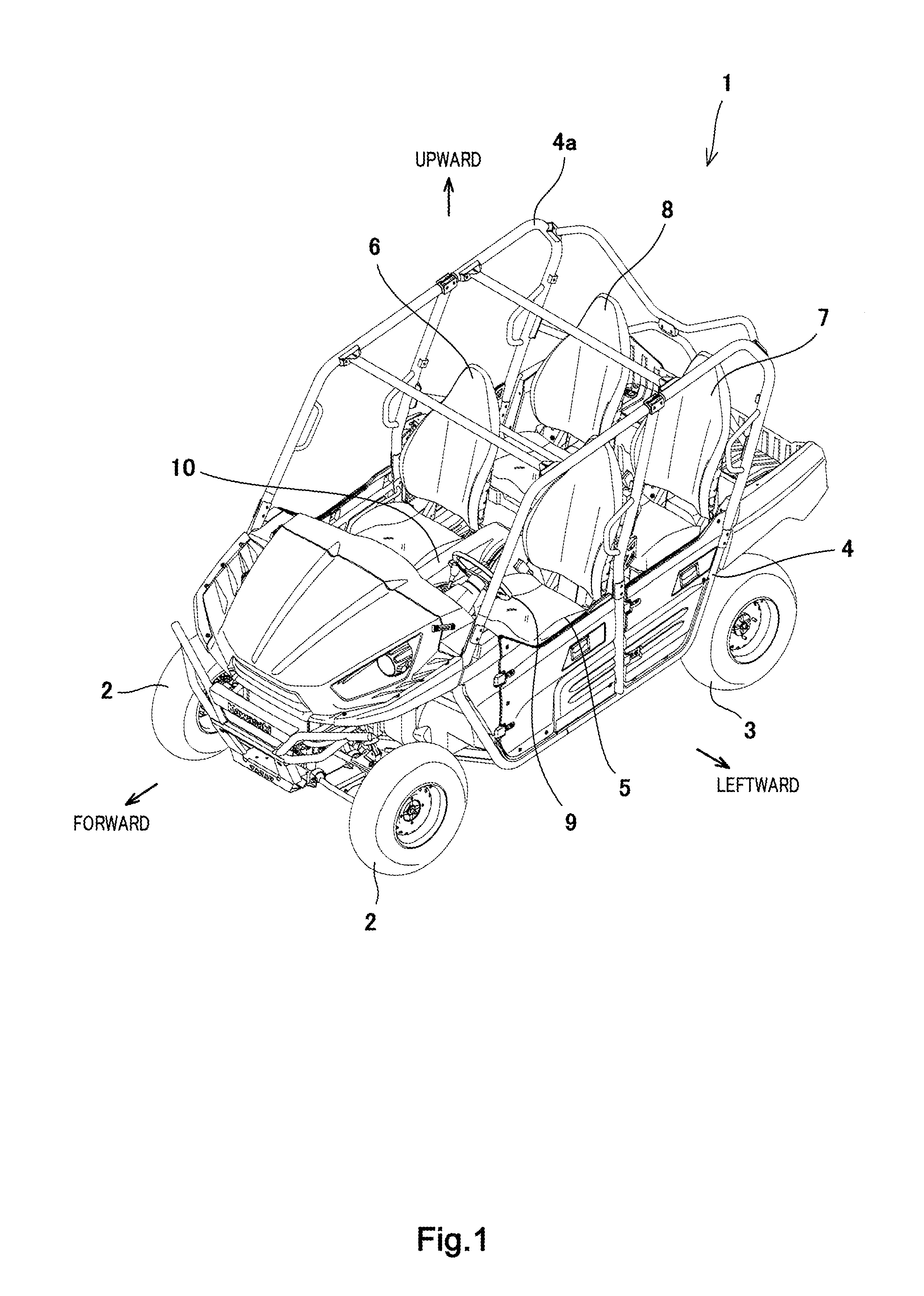
[0022]FIG. 1 is a perspective view showing an external appearance of the utility vehicle 1 (vehicle) according to an embodiment of the present invention. For example, the utility vehicle 1 is intended for four persons and has four wheels. The utility vehicle 1 includes a pair of right and left front wheels 2, a pair of right and left rear wheels 3, a vehicle body frame 4, a driver seat 5, a passenger seat 6, a left rear seat 7, and a right rear seat 8. The front wheels 2 are suspended from the front portion of the vehicle body frame 4, while the rear wheels 3 are suspended from the rear portion of the vehicle body frame 4. The four se...


PUM


Abstract

A belt-type continuously variable transmission comprises a drive pulley assembly mounted to a drive shaft; a driven pulley assembly mounted to a driven shaft; a belt connecting the two; and a case assembly for accommodating these components. The drive pulley assembly has fins for generating a flow of air moving toward an outer periphery of the drive pulley assembly. When viewed in an axial direction of the drive shaft, an air blocking plate is positioned at a forward side in a rotational direction of the drive pulley assembly relative to an imaginary line segment connecting a center axis of the drive pulley assembly to a center axis of the driven pulley assembly, between the drive pulley assembly and the driven pulley assembly such that the air blocking plate surrounds the outer periphery of the drive pulley assembly over a predetermined range.

Description

BACKGROUND OF THE INVENTION[0001]1. Field of the Invention[0002]The present invention relates to a belt-type continuously variable transmission incorporated into a vehicle. Particularly, the present invention relates to a cooling structure of the belt-type continuously variable transmission.[0003]2. Description of the Related Art[0004]United States Patent Application Publication No. 2010 / 0167853 discloses a cooling structure of a conventional V-belt-type continuously variable transmission (CVT) built into a utility vehicle. In the continuously variable transmission disclosed in this literature, a fixed sheave of a drive pulley and a fixed sheave of a driven pulley are provided with fins which function as centrifugal fans, and air introduced from outside into a case is flowed through the drive pulley and then the driven pulley, thereby cooling these pulleys and a V-belt.[0005]An air-intake duct is mounted to the peripheral wall of the case surrounding the drive pulley. Outside air su...

Claims


Application Information

Patent Timeline
Patent Type & Authority Patents(United States)
IPC IPC(8): F16H57/04
CPCF16H57/0416F16H57/0489
Inventor ITOO, SEIJIKII, HIDEAKI
Owner KAWASAKI MOTORS LTD
Why Eureka
Try Eureka