Disk drive motor

a drive motor and drive shaft technology, applied in the direction of record information storage, magnetic circuit shape/form/construction, instruments, etc., can solve the problem of not removing the yoke, and achieve the effects of reducing the linear expansion coefficient, and reducing the vibration and shock

Active Publication Date: 2014-09-16
MINEBEAMITSUMI INC
View PDF8 Cites 4 Cited by
  • Summary
  • Abstract
  • Description
  • Claims
  • Application Information

AI Technical Summary

Benefits of technology

[0009]The present invention provides a disk drive motor including a disk clamp mechanism with high reliability while employing a configuration of strongly fixing a back yoke to a turntable part by an adhesive.
[0011]According to the above configuration, the back yoke made of metal and the rotor frame made of metal are adhered and fixed using the adhesive, and there is little difference in the linear expansion coefficient. Therefore, there is no concern about the peeling off due to change in temperature or time and the back yoke can be securely fixed to the turntable part with the sufficient strength. Also, the back yoke is not removed from the turntable part due to the repetitive mounting and demounting of the clamper and the severe vibration and shock. Therefore, according to the present invention, it is possible to realize a disk drive motor including a disk clamp mechanism with high reliability.

Problems solved by technology

Also, the back yoke is not removed from the turntable part due to the repetitive mounting and demounting of the clamper and the severe vibration and shock.

Method used


Image

  • Disk drive motor
  • Disk drive motor
  • Disk drive motor

Examples


embodiments

[0023](Embodiments)

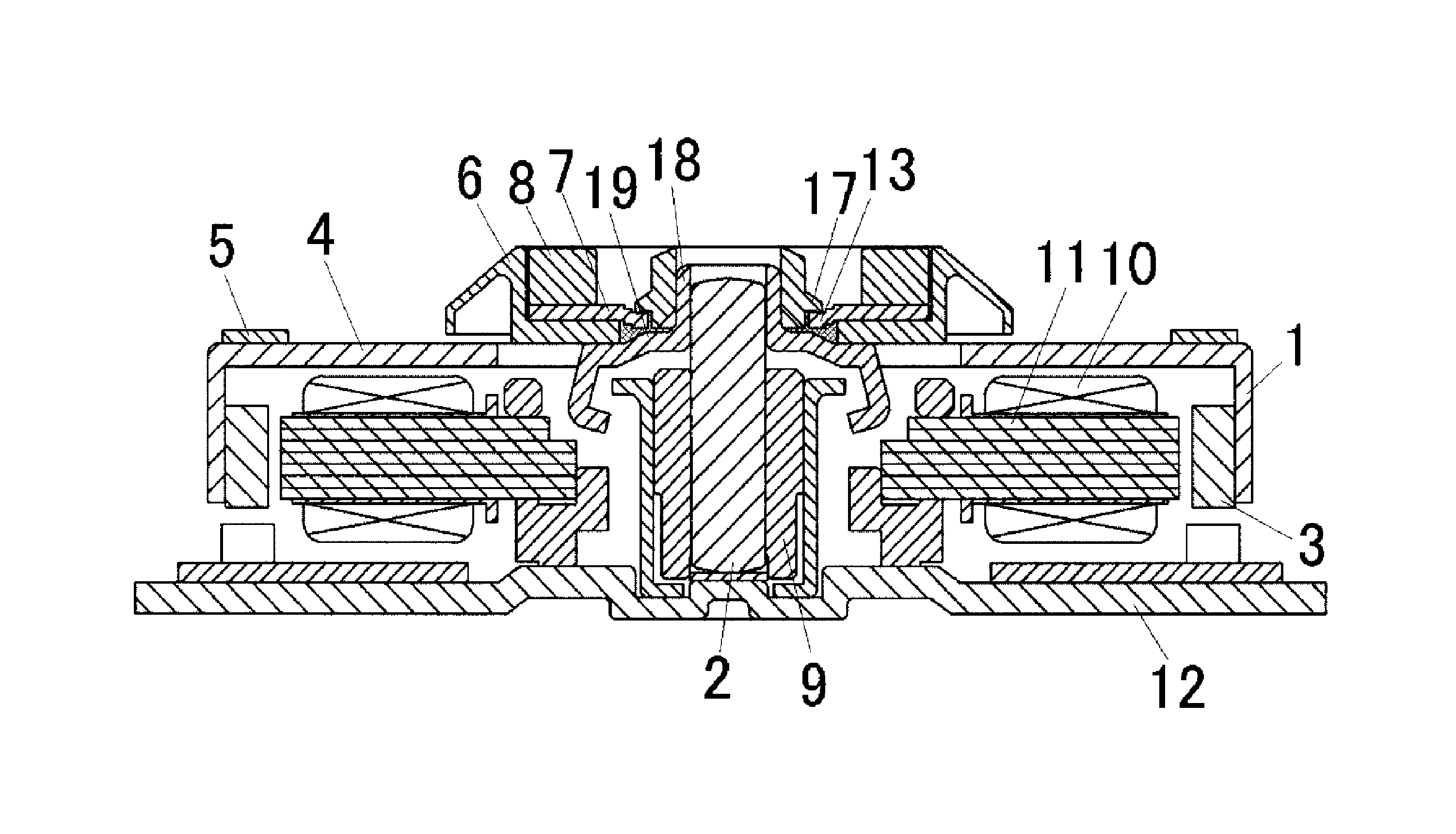
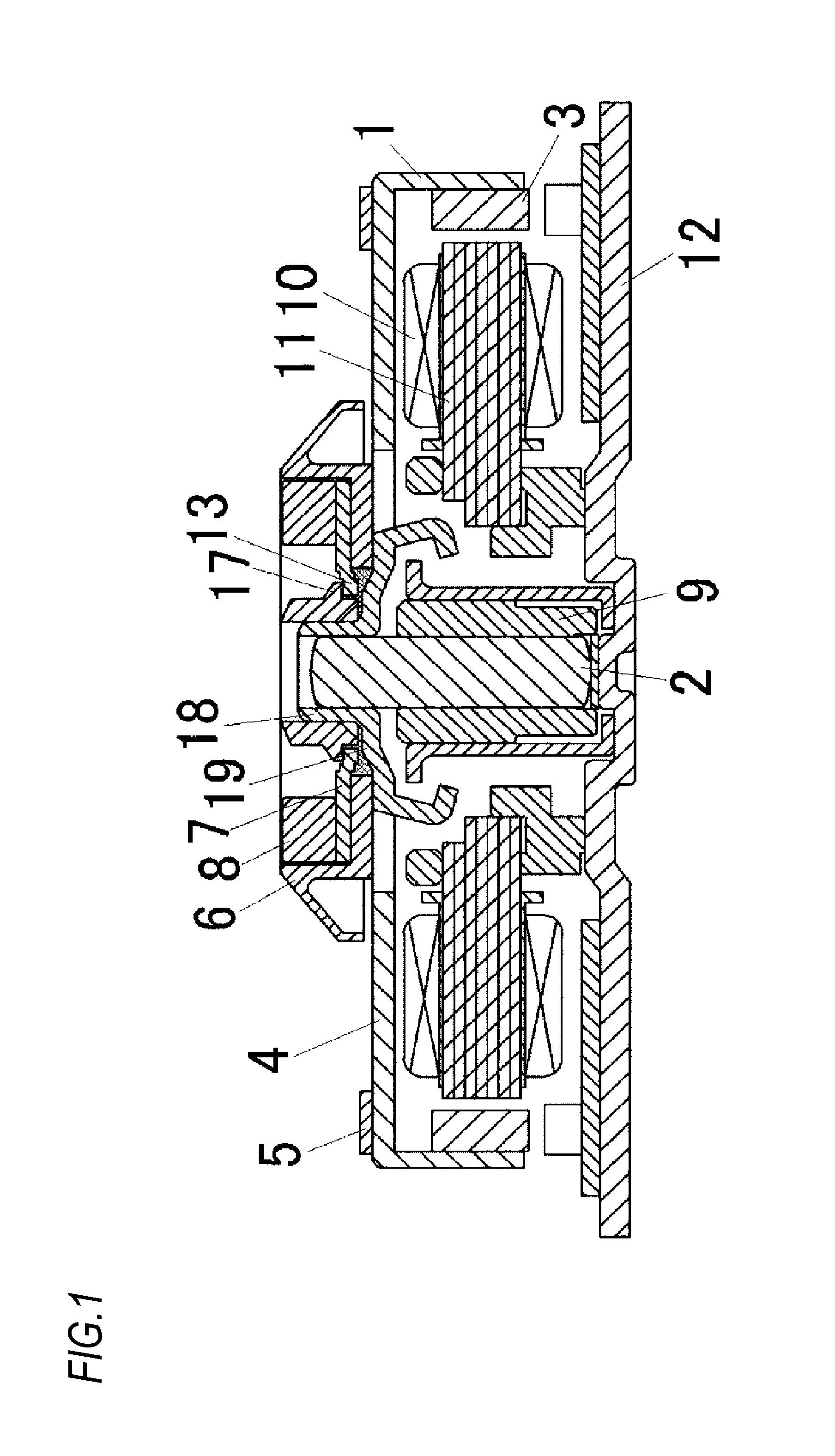
[0024]FIG. 1 is a sectional view of a disk drive motor according to an embodiment of the present invention.

[0025]First, a schematic configuration of the disk drive motor is described. In FIG. 1, the disk drive motor mainly includes a rotor assembly and a stator assembly.

[0026]The rotor assembly includes a rotor frame 1, a shaft 2, a rotor magnet 3, a rubber sheet 5, an alignment ring 6, a back yoke 7 and a clamp magnet 8. The rotor frame 1 has a substantial cup shape. The shaft 2 is fixed to the rotor frame 1. The rotor magnet 3 is fixed on an inner periphery of the rotor frame 1 and has a ring shape. The rubber sheet 5 is attached to a turntable part 4 of an upper surface of the rotor frame 1. The alignment ring 6 is provided to align an inner diameter part of a disk and has a substantially circular shape. The back yoke 7 and the clamp magnet 8 are accommodated in the alignment ring 6.

[0027]In the meantime, the stator assembly includes a bearing 9, a stator core ...


PUM

PropertyMeasurementUnit
inner diameteraaaaaaaaaa
shapeaaaaaaaaaa
speedaaaaaaaaaa

Abstract

A ring-shaped back yoke and a ring-shaped magnet are provided on a bottom surface of a ring-shaped opening part formed at a central portion of an alignment ring of a turntable part. The back yoke is provided with a protruding pawl which protrudes in a direction perpendicular to a plane of the back yoke, and the alignment ring is provided with a through hole into which the protruding pawl is inserted when mounting the back yoke to the alignment ring. The protruding pawl of the back yoke and an upper surface of a rotor frame are fixed together using an adhesive.

Description

TECHNICAL FIELD[0001]The present invention relates to a disk drive motor which is mainly used in a personal computer and an AV device, and more particularly, to a configuration of a turntable.BACKGROUND ART[0002]In a media recording and reproducing device using a media disk, a turntable is fixed to a shaft of a spindle motor provided to the device, a disk is loaded and rotated on a disk loading surface of the turntable, and information is written and read out to and from the disk. The turntable having the media disk loaded thereon is rotated at high speed. Hence, when the loaded disk has a slight deviation or deflection with respect to an in-plane center of gravity, a rotation center of the disk in the plane is deviated due to a surface swinging. Therefore, an optical pickup of reading information from a track of the disk or recording information to a track of the disk is deviated from the track.[0003]Hence, in order to further increase the jointing force of the rotating media disk,...

Claims


Application Information

Patent Timeline
Patent Type & Authority Patents(United States)
IPC IPC(8): H02K7/00H02K7/08G11B17/04G11B17/28G11B17/028G11B19/20
CPCG11B17/0282G11B19/2009
Inventor NISHIKATA, TOSHIYUKINOTO, HIDEKI
Owner MINEBEAMITSUMI INC
Why Eureka
Try Eureka