Vehicle drive device

a technology for driving devices and vehicles, applied in the direction of capacitor propulsion, battery/cell propulsion, gearing, etc., can solve the problems of increasing the size and manufacturing cost affecting the operation of vehicle drive devices, and affecting the relative movement in the axial direction between the coupling output side member and the driven member in some cases. , to achieve the effect of increasing the size of the supporting bearing

Active Publication Date: 2014-09-16
AISIN AW CO LTD +1
View PDF90 Cites 17 Cited by
  • Summary
  • Abstract
  • Description
  • Claims
  • Application Information

AI Technical Summary

Benefits of technology

[0007]It is therefore desired to implement vehicle drive devices capable of suppressing an increase in size of a support bearing even when a coupling input-side member may move in the axial direction due to an attractive force that is generated between the coupling input-side member and a coupling output-side member of a fluid coupling.
[0012]According to the first aspect, the rotor main body of the rotating electrical machine can be appropriately rotatably supported on the axial first direction side with respect to the coupling input-side member by the rotor support member that is rotatably supported in the radial direction by the case via the support bearing. In the first aspect, the movement restricting mechanism restricts the axial movement of the power transmission member, which is formed by coupling the rotor support member and the coupling input-side member so that the rotor support member and the coupling input-side member rotates together, toward the axial first direction side. Thus, even if the coupling input-side member is moved in the axial first direction by an attractive force that is applied between the coupling input-side member and the coupling output-side member of the fluid coupling due to a difference in rotational speed therebetween, the movement restricting mechanism can suppress application of an axial load to the support bearing via the power transmission member. Thus, the support bearing need not be reinforced even in such a case, and an increase in size of the support bearing can be suppressed.
[0014]According to the second aspect, the restricting bearing that rotatably supports the power transmission member in the axial direction is provided separately from the support bearing, and the restricting bearing is supported from the axial first direction side by the axial support portion of the case. Thus, the movement restricting mechanism that restricts the axial movement of the power transmission member in the axial first direction can be appropriately structured. This can more reliably prevent the axial load from being applied to the support bearing.
[0018]According to the fourth aspect, the rotor support member and the rotor main body can be appropriately rotatably supported on the outer peripheral surface of the cylindrical protruding portion of the support wall provided in the case via the support bearing. Moreover, in this fourth aspect, the movement restricting mechanism using the end of the cylindrical protruding portion on the axial second direction side can rotatably support the cover portion of the coupling input-side member in the axial direction. Thus, a mechanism that restricts the axial movement of the power transmission member on the axial first direction side can be structured in a compact manner by using the cylindrical protruding portion for rotatably supporting the rotor support member and the rotor main body.
[0020]According to the fifth aspect, the internal combustion engine that is drivingly coupled to the engagement input-side member via the input member, and the rotating electrical machine that is drivingly coupled to the engagement output-side member can be selectively drivingly coupled together by the engagement device. Thus, for example, in the case where a vehicle travels only by output torque of the rotating electrical machine, energy loss due to drag loss of the internal combustion engine can be suppressed.
[0021]Moreover, in this fifth aspect, the input-side radially extending portion of the input member extends in the radial direction between the cylindrical protruding portion and the fluid coupling in the axial direction. However, since the restricting bearings separate from the support bearing are provided between the cylindrical protruding portion and the input-side radially extending portion, and between the input-side radially extending portion and the power transmission member, respectively, the input member that is coupled to the engagement input-side member can be appropriately supported in the axial direction. Furthermore, by using the end of the cylindrical protruding portion on the axial second direction side, the cover portion can be appropriately supported in the axial direction with respect to the cylindrical protruding portion via the input-side radially extending portion and the two restricting bearings.

Problems solved by technology

However, the study by the inventors showed that relative movement in the axial direction between the coupling output-side member and the driven member may not be appropriately implemented in some cases.
Thus, in the structure of the device of Japanese Patent No. 3080612, the support bearing needs to have such capability that can resist this axial load, which necessarily results in an increase in size of the support bearing.
Increasing the size of the support bearing is not preferable because such increase leads to an increase of the size and manufacturing cost of vehicle drive devices.

Method used


Image

  • Vehicle drive device
  • Vehicle drive device
  • Vehicle drive device

Examples


Embodiment Construction

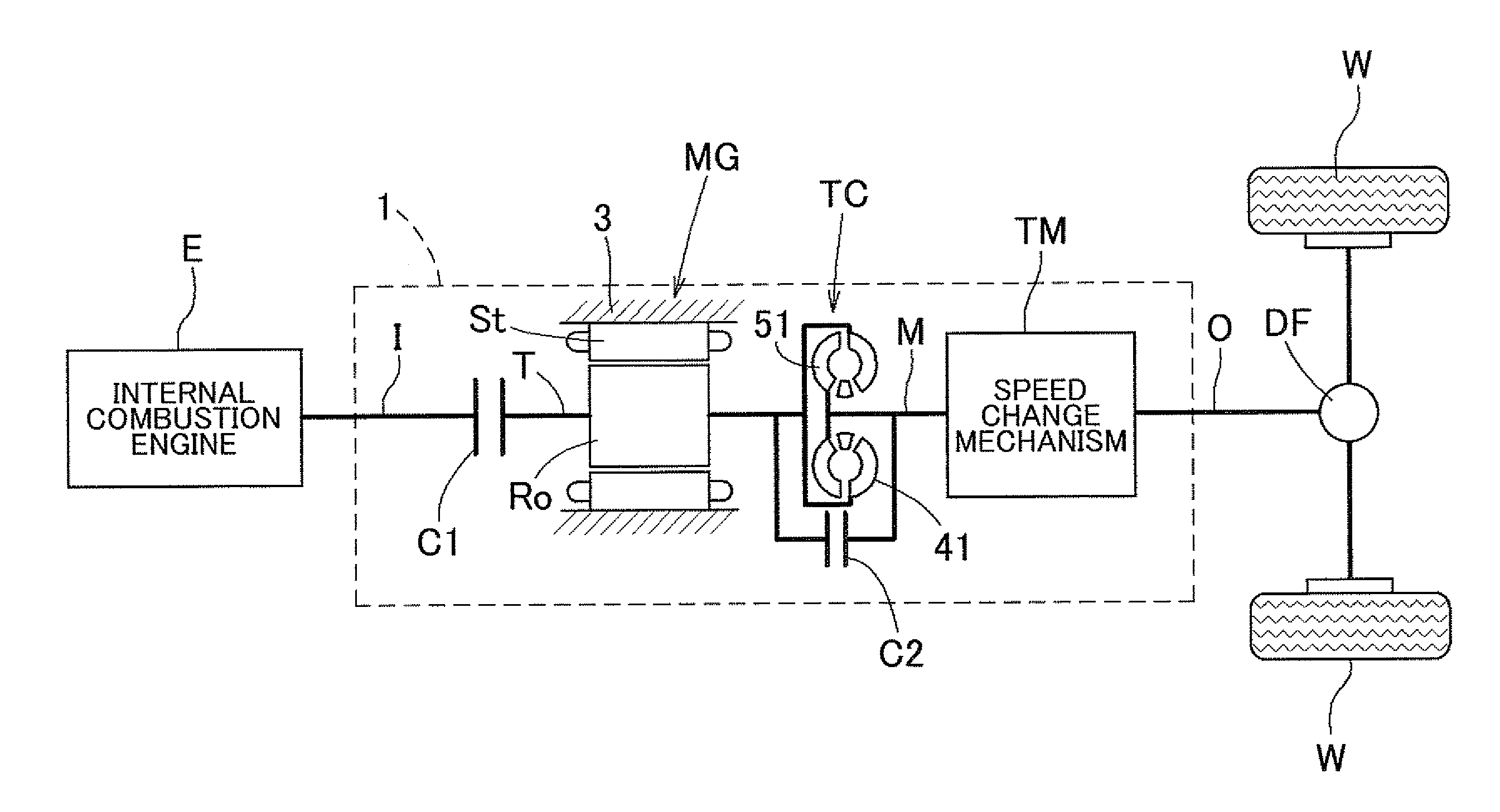
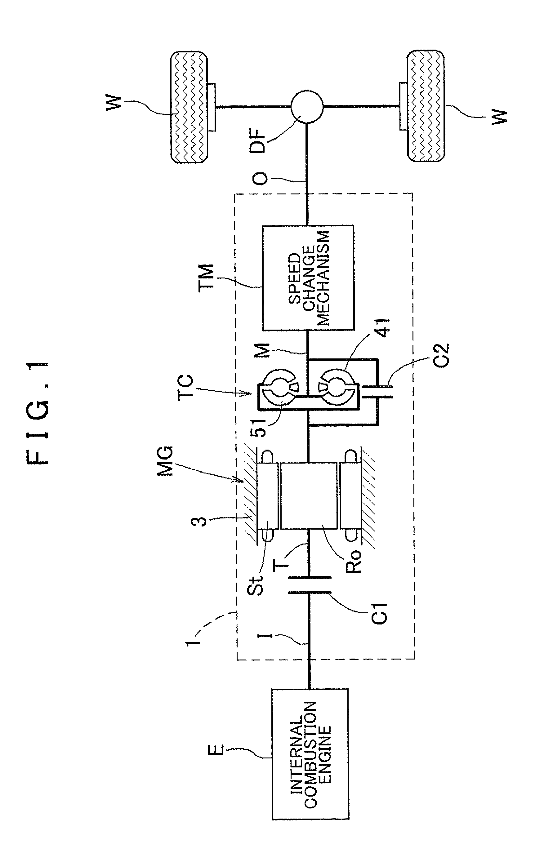
[0032]An embodiment of the present invention will be described below with reference to the accompanying drawings. As shown in FIG. 1, a drive device 1 is a drive device for hybrid vehicles (a hybrid drive device) using one or both of an internal combustion engine E and a rotating electrical machine MG as a driving force source of a vehicle. The drive device 1 is structured as a drive device for so-called one-motor parallel type hybrid vehicles. The drive device 1 of the present embodiment will be described in detail below.

1. Overall Structure of Drive Device

[0033]First, the overall structure of the drive device 1 of the embodiment will be described below. As shown in FIG. 1, the drive device 1 includes an input shaft I drivingly coupled to the internal combustion engine E as a first driving force source of a vehicle, an output shaft O drivingly coupled to wheels W, the rotating electrical machine MG as a second driving force source of the vehicle, and a torque converter TC. The driv...


PUM


Abstract

A vehicle drive device includes an input member coupled to an internal combustion engine; an output member coupled to a wheel; a rotating electrical machine; a fluid coupling; and a case containing at least the rotating electrical machine and the fluid coupling. The fluid coupling includes an input and an output that is paired with the input. The rotating electrical machine includes a rotor and a rotor support that extends radially inward from the rotor in an axial direction with respect to the coupling input, and supports the rotor via a support bearing. A power transmission member is formed by coupling at least the rotor support and the coupling input together so that at least the rotor support and the coupling input rotate together. A movement restricting mechanism restricts axial movement of the power transmission member toward the axial direction.

Description

INCORPORATION BY REFERENCE[0001]The disclosure of Japanese Patent Applications No. 2009-264381 filed on Nov. 19, 2009, No. 2010-049192 filed on Mar. 5, 2010, No. 2010-049193 filed on Mar. 5, 2010, and No. 2010-246514 filed on Nov. 2, 2010 including the specification, drawings and abstract is incorporated herein by reference in its entirety.BACKGROUND OF THE INVENTION[0002]The present invention relates to vehicle drive devices including an input member drivingly coupled to an internal combustion engine, an output member drivingly coupled to wheels, a rotating electrical machine, a fluid coupling, and a case accommodating at least the rotating electrical machine and the fluid coupling.DESCRIPTION OF THE RELATED ART[0003]A device described in, e.g., Japanese Patent No. 3080612 below is known as such a vehicle drive device. As shown in FIG. 1 of Japanese Patent No. 3080612, in this vehicle drive device, a rotor support member (a rotor 8) that supports a rotor main body of a rotating ele...

Claims


Application Information

Patent Timeline
Patent Type & Authority Patents(United States)
IPC IPC(8): H02K7/108B60K6/442B60K6/26B60K6/405B60K6/48B60K6/547F16H45/00F16H57/04
CPCB60K6/48B60K6/547B60K6/26B60K6/405F16H57/0473Y02T10/6221F16H57/0471F16H2045/002F16H57/0476B60L15/2054B60L2240/486B60L2240/507Y02T10/72B60L50/40B60L50/61Y02T10/62Y02T10/70Y02T10/64Y02T10/7072
Inventor IWASE, MIKIOSUZUKI, TOMOHIDEJINNAI, NAOYAOKISHIMA, TATSUYAKAMIYA, TOSHIHIKO
Owner AISIN AW CO LTD
Why Eureka
Try Eureka