Camera arrangement for a vehicle and method for installing a camera arrangement in a vehicle

a technology for installing a camera and a vehicle, which is applied in the direction of color television, television systems, transportation and packaging, etc., can solve the problems of corrosion damage and the inability of the camera unit to visually detect the surrounding area of the vehicle in the inactive position

Inactive Publication Date: 2014-09-16
AUDI AG
View PDF36 Cites 11 Cited by
  • Summary
  • Abstract
  • Description
  • Claims
  • Application Information

AI Technical Summary

Benefits of technology

[0007]It is therefore an object of the present invention to provide a compact and inexpensive camera arrangement for a vehicle, wherein the camera arrangement is protected from vandalism and the weather, and a method for installing such a camera assembly in a vehicle.
[0009]Because the sealing cover on the camera unit closes the opening to the chamber in the inactive position and the camera unit closes the opening in the active position, neither particles nor moisture can enter the chamber in the two end positions of the camera unit and cause corrosion damage. In addition, the camera arrangement can attain a compact and advantageous design by attaching the sealing means on the camera unit. Pivoting the camera unit inherently causes the sealing means to contact the respective components. The sealing cover may be formed on or attached to the camera unit as an additional component. Electronic components necessary to use the camera unit and the drive needed to pivot the camera unit can also be arranged inside the chamber. The camera unit is unable to visually detect the surrounding area of the vehicle in the inactive position. The camera unit typically remains in the inactive position to protect the camera unit from vandalism. The camera unit is pivoted into the active position and image capture is activated only when the vehicle operator desires a visual display of the respective surrounding area of the vehicle, for example to facilitate maneuvering.
[0012]In a preferred embodiment, the camera unit can be pivoted with a spindle drive. A spindle drive allows a particularly compact drive design. The spindle drive cooperates with a toothed portion formed on the camera unit in the form of a worm gear.
[0016]In a preferred embodiment, an operating device to operate the lid or door is included in the housing module. When the housing module additionally accommodates an operating means for unlocking a lid or door, both functions can be inexpensively and easily incorporated in the housing module. When a camera unit is not to be installed some situations, the chamber in the camera module can be closed by a blank cover on the operating module.
[0017]In a preferred embodiment, the sealing cap is positively secured to the camera unit. The positive connection between the sealing cap and the camera unit enables quick assembly.
[0025]The installation of a camera arrangement in a vehicle according to the aforedescribed method has the advantage that the valuable camera module is arranged inside the lid or door and protected from theft. The body opening is selected to be just large enough so that the camera module cannot be removed through the body opening from the outside. The camera module and the externally introduced operating module are preferably interconnected by clips, which can not be disengaged again without being destroyed. By attaching the sealing cover to the camera unit in a final step, the opening of the chamber, through which the camera unit is pivoted, can extend as closely as possible around the camera unit. This has a positive effect on the sealing properties of the sealing cap. The edge of the camera unit preferably seals in the active position against the operating module. The camera module may again be composed of two housing halves to facilitate installation of the camera unit, the actuator and the electronic components.

Problems solved by technology

Because the sealing cover on the camera unit closes the opening to the chamber in the inactive position and the camera unit closes the opening in the active position, neither particles nor moisture can enter the chamber in the two end positions of the camera unit and cause corrosion damage.
The camera unit is unable to visually detect the surrounding area of the vehicle in the inactive position.

Method used


Image

  • Camera arrangement for a vehicle and method for installing a camera arrangement in a vehicle
  • Camera arrangement for a vehicle and method for installing a camera arrangement in a vehicle
  • Camera arrangement for a vehicle and method for installing a camera arrangement in a vehicle

Examples


Embodiment Construction

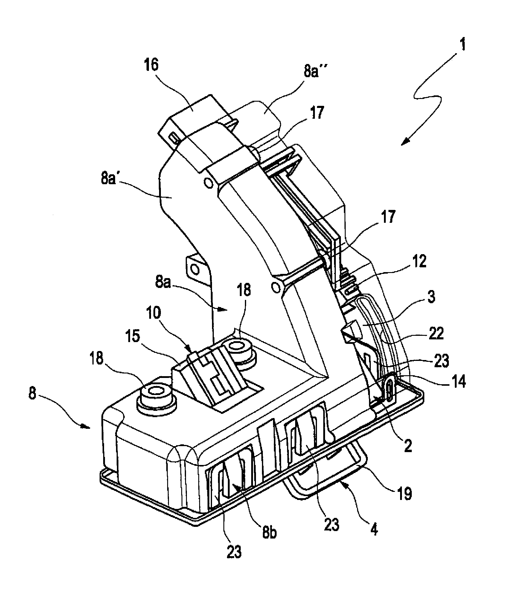
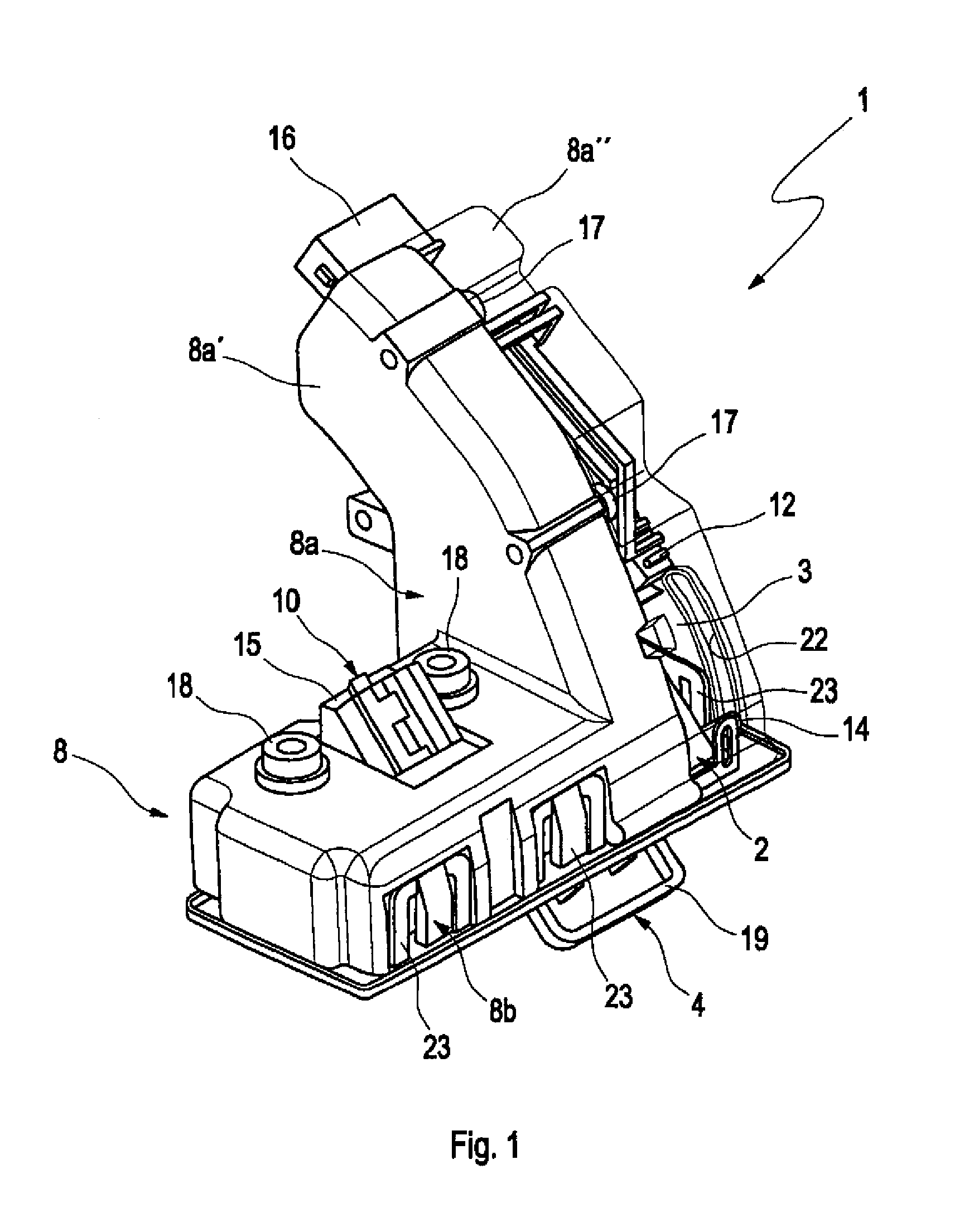
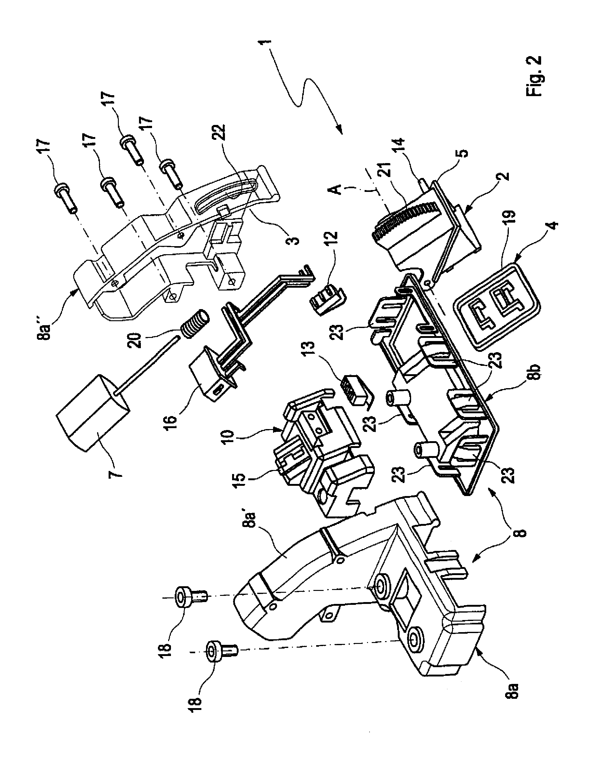
[0032]FIG. 1 shows an camera arrangement 1 according to the present invention in an active position, with FIG. 2 showing the same camera arrangement 1 in an exploded view. The housing module 8 is composed of a camera module 8a and an operating module 8b. The camera module 8a is in turn composed of two housing halves 8a′ and 8a″. An operating device 10 with an electrical connection 15 and an operating switch 13 is mounted on the actuation module 8b. The operating module 8b is at least partially made of a soft component, wherein the operating switch 13 is arranged in the region of this soft component. Operation of the operating switch 13 triggers unlocking of a door or lid of the vehicle. The camera unit 2 is installed in a chamber 3 of the camera module 8a. The camera unit 2 can be pivoted about a pivot axis A and is guided via a guide pin 14 in a slide gate 22 of the second housing half 8a″. The camera unit 2 which has a substantially cubic shape has a diagonal edge 5, which extends...


PUM


Abstract

A camera arrangement for a vehicle, with a camera unit constructed to be pivoted between an active position and an inactive position, and a chamber accommodating the camera unit, wherein in the inactive position a sealing cover that seals the chamber is arranged on the camera unit, with the camera unit being inaccessible from outside, and wherein in the active position the camera unit is pivoted out of the chamber for optically capturing a surrounding area and the camera unit seals the chamber. A method for installing the camera arrangement in a vehicle is also disclosed.

Description

CROSS-REFERENCES TO RELATED APPLICATIONS[0001]This application is the U.S. National Stage of International Application No. PCT / EP2011 / 003987, filed Aug. 10, 2011, which designated the United States and has been published as International Publication No. WO 2012 / 034621 A1 and which claims the priority of German Patent Application, Serial No. 10 2010 045 214.9, filed Sep. 13, 2010, pursuant to 35 U.S.C. 119(a)-(d).BACKGROUND OF THE INVENTION[0002]Camera arrangements of this type are integrated into the body of vehicles for letting the driver comfortably observe the vehicle surroundings, in particular the rear portion of the vehicle. This occurs preferably by a motion playback of the image captured from the camera on a monitor mounted in the interior of the vehicle.[0003]DE 10 2008 010 966 A1 discloses an arrangement for a vehicle with an unlocking device for unlocking a component of the vehicle, wherein the unlocking device includes a cover element that can be pivoted from a rest posi...

Claims


Application Information

Patent Timeline
Patent Type & Authority Patents(United States)
IPC IPC(8): H04N7/18B60R11/00B60R11/04H04N5/225
CPCH04N5/2251B60R11/04B60R2011/0085H04N23/50B60R11/00B60R1/08B60R1/00
Inventor LIEPOLD, THOMASBOHM, GUNTHER
Owner AUDI AG
Why Eureka
Try Eureka