
Molding machine with closed hydraulic drive system

A drive system and molding machine technology, applied in the direction of fluid pressure actuators, mechanical equipment, servo motors, etc., to achieve high energy efficiency

Active Publication Date: 2021-12-07
ENGEL AUSTRIA
View PDF13 Cites 0 Cited by
  • Summary
  • Abstract
  • Description
  • Claims
  • Application Information

AI Technical Summary

Problems solved by technology

However, this has the disadvantage that the clamping force device must be clamped on the column in another step and by another drive

Method used


Image

  • Molding machine with closed hydraulic drive system
  • Molding machine with closed hydraulic drive system
  • Molding machine with closed hydraulic drive system

Examples


Embodiment Construction

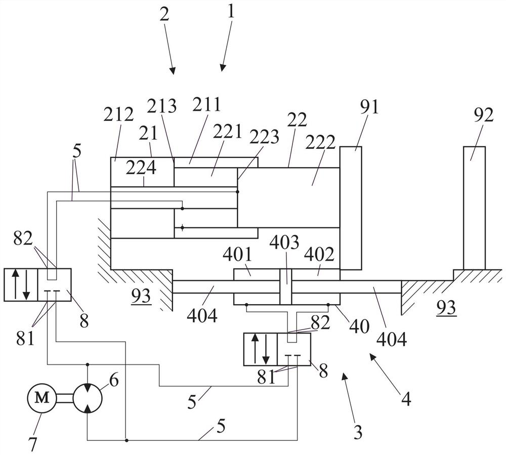
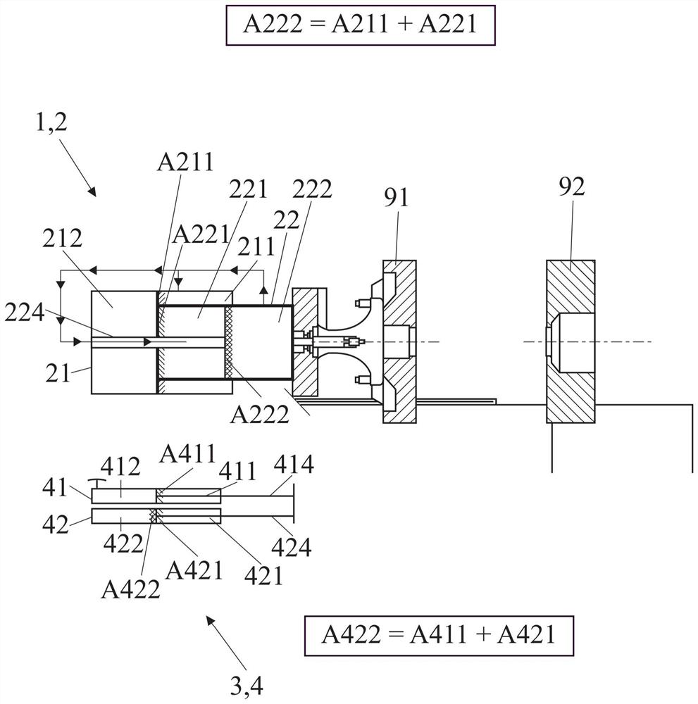
[0135] figure 1 A schematic diagram of a closed hydraulic system is shown, which includes the actuator 2 of the mold clamping force device 1 and the actuator 4 of the quick stroke device 3 for applying force to the movable mold clamping plate 91 . Also shown are the fixed mold clamping plates 92 and the machine frame 93 of the forming machine 9 . The two actuators 2 , 4 are driven with hydraulic fluid via a hydraulic line 5 by a pump 6 driven by an electric motor 7 . The hydraulic drive can also have several pumps 6 and / or several electric motors 7 .

[0136] In this case, a switching element 8 is arranged between the pump 6 and the actuator 2 of the clamping force device 1 and the pump 6 and the actuator 4 of the rapid stroke device 3 . The switching element 8 can be formed as a 2-port / 2-way valve (2-Port / 2-Wege-Ventil), thus having two connections 81 on the side of the pump 6 and two connections on the side of the actuators 2, 4 82. Furthermore, the two switching element...


PUM


Abstract

A molding machine (9), in particular an injection molding machine or an injection molding machine, comprises: a machine frame (93); a mold clamping plate (91) movably supported on the machine frame (93); a fixed mold clamping plate (92), arranged on the machine frame (93); a quick travel device (3) for opening and closing the movable mold clamping plate (91) by means of at least one actuator (4); a hydraulic drive system for driving at least one actuator (4); wherein the hydraulic drive system is designed as a closed hydraulic system, the molding machine (9) further comprises a clamping force device (1) for forming a clamping force by means of at least one further actuator (2), and the hydraulic drive system further comprises at least one switching element (8) having at least two switching positions. Therefore, the at least one actuator of the rapid stroke device or the at least one actuator of the clamping force device can be selectively driven by the at least one pump according to the switch position.

Description

technical field [0001] The invention relates to a molding machine with the features of the preamble of claim 1 and a method for moving a mold clamping plate and for generating a clamping force on a clamping unit of a molding machine with the features of the preamble of claim 28 . Background technique [0002] The clamping unit of a molding machine typically includes partially movable mold clamps with which the mold is clamped and placed under pressure. These mold jaws have to be moved on the one hand and to build up high pressures on the mold on the other hand. [0003] In order to achieve this, it is known from the prior art to use separate drives for both purposes: the rapid stroke device is responsible for the movement, while the clamping force device can exert a high pressure on the mould. [0004] The mold closing method therefore consists of two steps: moving the mold jaws by means of a rapid stroke device in order to close the mold and building up pressure on the mo...

Claims


Application Information

Patent Timeline
Patent Type & Authority Applications(China)
IPC IPC(8): B29C45/67B29C43/32F15B11/22F15B11/16F15B13/06
CPCB29C45/67B29C45/82B29C2045/1768B29C43/32F15B11/22F15B11/16F15B13/06B29C2043/3272B29C45/68
Inventor P·巴德尔K·H·盖特林格
Owner ENGEL AUSTRIA
Learn More