
Door opening/closing structure

a technology for opening/closing structures and doors, which is applied in the direction of hinges, manufacturing tools, wing accessories, etc., can solve the problems of difficult attachment/detachment of doors, difficult to attach/detach doors, and not intended for attachment/detachment of doors, so as to reduce the quantity of stock, reduce the cost, and facilitate the effect of stock managemen

Inactive Publication Date: 2014-09-23
YAGIKEN
View PDF22 Cites 11 Cited by
  • Summary
  • Abstract
  • Description
  • Claims
  • Application Information

AI Technical Summary

Benefits of technology

Enables easy replacement of doors with different designs, reduces manufacturing costs, and allows for flexible application to various dimensional accuracies, facilitating easy and secure attachment and detachment.

Problems solved by technology

However, these conventional door opening / closing structures are not intended for attachment / detachment of the door.
Therefore, if the door is tried to be detached from the main body, it is not easy to attach and detach the door because of the interruption between the concavity and convexity of the axial members and the bearings.
However, this hinge is also included in a technique of fixing a door to an object to which the door is attached in the concave-convex engagement and if the door is tried to be detached from the main body, another means for releasing the concave-convex engagement fixation is required and thus the attachment / detachment of the door is not easy.

Method used


Image

  • Door opening/closing structure
  • Door opening/closing structure
  • Door opening/closing structure

Examples


first embodiment

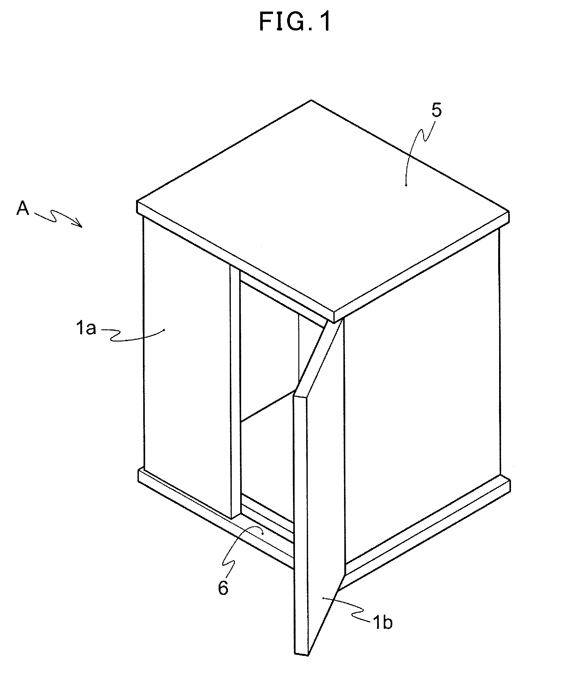
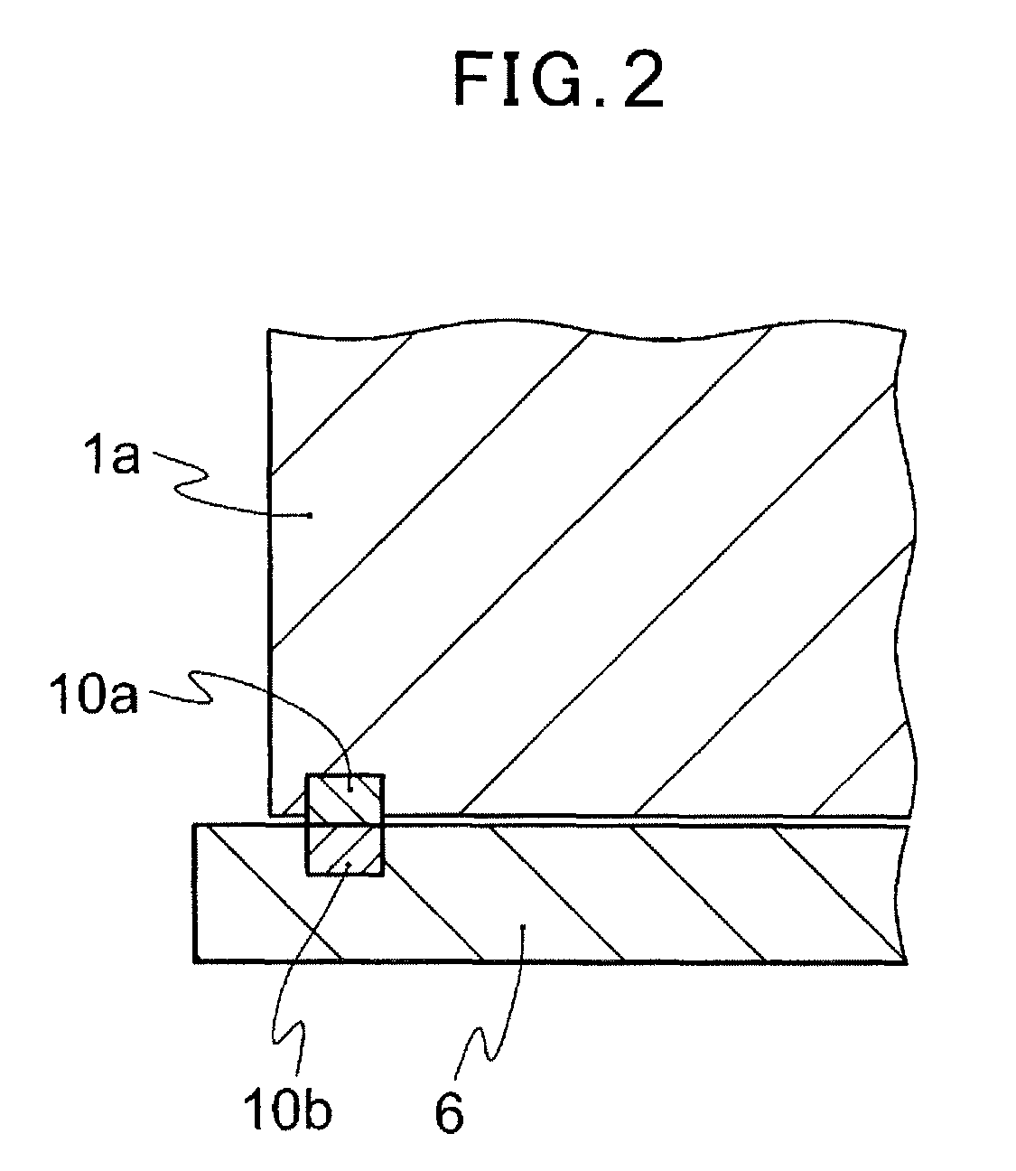
[0029]FIG. 1 is a schematic perspective view of furniture according to the present invention and FIG. 2 is a schematic sectional view of a door opening / closing structure provided in the furniture of FIG. 1.

[0030]As shown in FIG. 1, the furniture A is a wooden structure in a box shape having a top plate 5 and a bottom plate 6, and three lateral sides are covered and almost all of the front surface is open. In the both sides of the front surface of the furniture A, a left-and-right pair of doors1a and 1b which open and close in a gatefold manner are attached. The two doors 1a and 1b are a rectangular plate made of wood. The top and bottom of one side of the doors 1a and 1b are rotatably attached to the top plate 5 and the bottom plate 6 in a position anterior to the opening end of the front surface of the furniture A.

[0031]As shown in FIG. 2, in the bottom end of the door 1a, a cylindrical axial member (hereinafter, referred to as “first axial member”) 10a is fixed by embedding so as ...

fifth embodiment

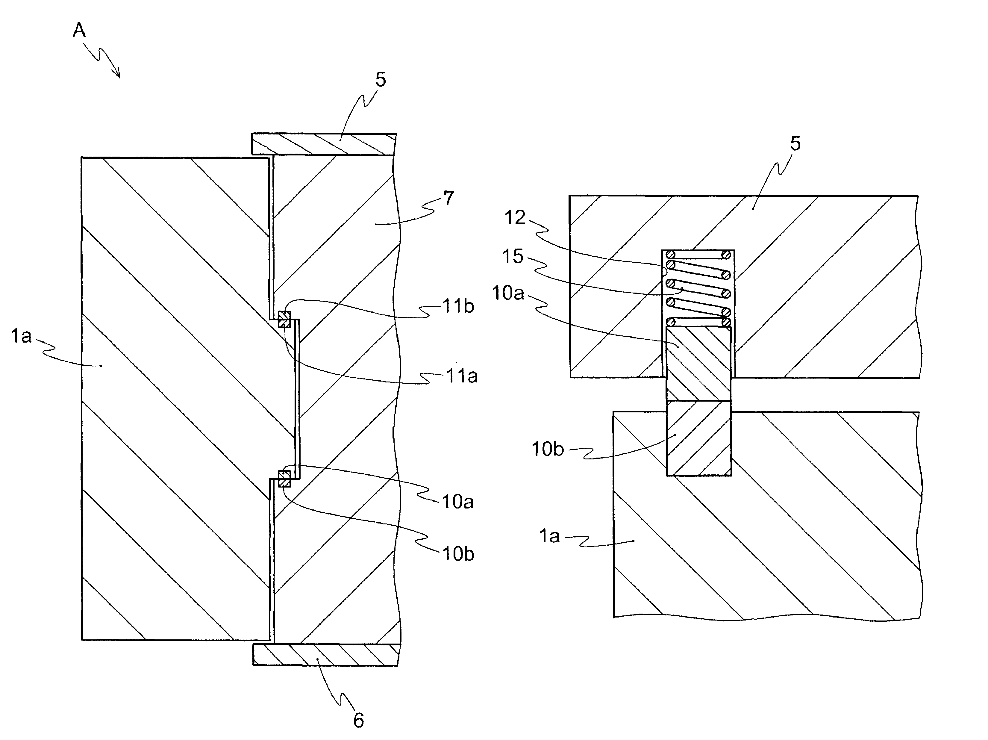
[0045]FIG. 9 is a schematic sectional view of a door opening / closing structure according to the present invention; and FIG. 10 corresponds to FIG. 9 and is a schematic sectional view of the object to which the door is attached before the door is attached. Since the configuration of the door opening / closing structure according to this embodiment is basically the same as that according to the forth embodiment which is explained above, the explanation will be focused on differences therebetween.

[0046]As shown in FIGS. 9 and 10, the door 1a according to the fifth embodiment is different from that according to the forth embodiment in that a flange 20 is formed on the upper side of a first axial member 10a over the outer circumference and the first axial member 10a has a T-shaped longitudinal section, and that a casing 16 is fixed by embedding in a concave portion formed on the bottom surface of the top plate 5 and a compression spring 15 and the first axial member 10a are contained in th...


PUM


Abstract

Provided is a door opening / closing structure in which the attachment / detachment of the door is easy in the rotatably opening / closing door. In the door opening / closing structure, an axial member attached to a door and an axial member attached to an object to which the door is attached are arranged to oppose each other in at least one position of the rotatably fixed door, wherein one of the two axial members comprises a magnet and the other comprises a magnetic body or a magnet which attracts each other with the magnet.

Description

TECHNICAL FIELD[0001]The present invention relates to a door opening / closing structure and more specifically, the present invention relates to an opening / closing structure of a door which opens / closes rotatably and is attached to buildings, furniture, ornaments and the like.BACKGROUND ART[0002]Rotatably opening / closing doors have been widely used for buildings, furniture, ornaments and the like and many of the opening / closing structures of such doors have an opening / closing structure in which an axial member (convex portion) and a bearing (concave portion) are rotatably fixed in the concave-convex engagement. In Patent Document 1, the basic configuration of the door opening / closing structure also provides bearings in the center line of rotation at the door side and the main body side, which is an object to which the door is attached, and axial members rotatably engages in both bearings. However, these conventional door opening / closing structures are not intended for attachment / detac...

Claims


Application Information

Patent Timeline
Patent Type & Authority Patents(United States)
IPC IPC(8): E05D15/00
CPCE05D7/1011E05D15/00Y10T16/5402Y10T16/5401E05Y2900/132E05D1/06E05D7/1061E05Y2201/474E06B7/28E05D7/00E05Y2201/46E05D2007/1027E05D7/1044E05D2005/104E05D7/081E05D7/10
Inventor YAGI, RYUUICHINAGAMINE, TAKAHISAHORIZUMI, MASAHIKO
Owner YAGIKEN
Learn More