Structure of roll-rod for subframe

a technology of roll-rods and subframes, which is applied in the direction of machine supports, shock absorbers, jet propulsion mountings, etc., can solve the problems of fatigue of materials and durability, large dynamic ratio (an increase ratio of dynamic load to static load), and difficulty in tuning

Active Publication Date: 2014-09-23
HYUNDAI MOTOR CO LTD
View PDF12 Cites 15 Cited by
  • Summary
  • Abstract
  • Description
  • Claims
  • Application Information

AI Technical Summary

Benefits of technology

[0021]A front stopper is mounted at an end of the outer pipe and faces the bracket bar to prevent an impact between the housing and the bracket bar.
[0022]A rear stopper is mounted on the endplate and faces the housing to prevent an impact between the housing and the endplate.
[0023]According to an exemplary embodiment of the present invention, dynamic ratio is reduced by controlling damping force depending on behavior of a vehicle, thereby improving NVH performance of the vehicle.
[0024]That is, in a structure of the present invention using a principle of a venture pipe, as a volume of a passage between a front liquid chamber and a rear liquid chamber varies, vibration transfer is minimized and impact is more efficiently dampened.
[0025]When an engine is idle, a hydro liquid easily flows (while a gap between a supporting plate and an extension part is relatively large), and as a result, vibration is more efficiently alleviated, and since the hydro liquid becomes difficult to flow (while the gap between the supporting plate and the extension part gradually decreases) in a quick start, larger impact can be absorbed. Further, the flow of the hydro liquid is controlled according to a traveling state and an acceleration of the vehicle even while travelling, such that traveling performance is further improved.
[0026]In addition, a front stopper and a rear stopper are mounted to prevent an insulator from being excessively elastically transformed, thereby improving durability.

Problems solved by technology

However, the rear bush in the related art using elastic force of a material has a problem in that dynamic ratio (an increase ratio of dynamic load to static load) is large and tuning is difficult (in order to meet design requirements).
Further, the elastic transformation and restoration of the rear bush cause a fatigue of a material and durability deteriorates in continuous use as a structure without an additional stopper (supporting to prevent elastic compression of a predetermined reference or more).

Method used


Image

  • Structure of roll-rod for subframe
  • Structure of roll-rod for subframe
  • Structure of roll-rod for subframe

Examples


Embodiment Construction

[0037]Reference will now be made in detail to various embodiments of the present invention(s), examples of which are illustrated in the accompanying drawings and described below. While the invention(s) will be described in conjunction with exemplary embodiments, it will be understood that the present description is not intended to limit the invention(s) to those exemplary embodiments. On the contrary, the invention(s) is / are intended to cover not only the exemplary embodiments, but also various alternatives, modifications, equivalents and other embodiments, which may be included within the spirit and scope of the invention as defined by the appended claims.

[0038]Hereinafter, a roll-rod for a subframe according to an exemplary embodiment of the present invention will be described in more detail with reference to the accompanying drawings.

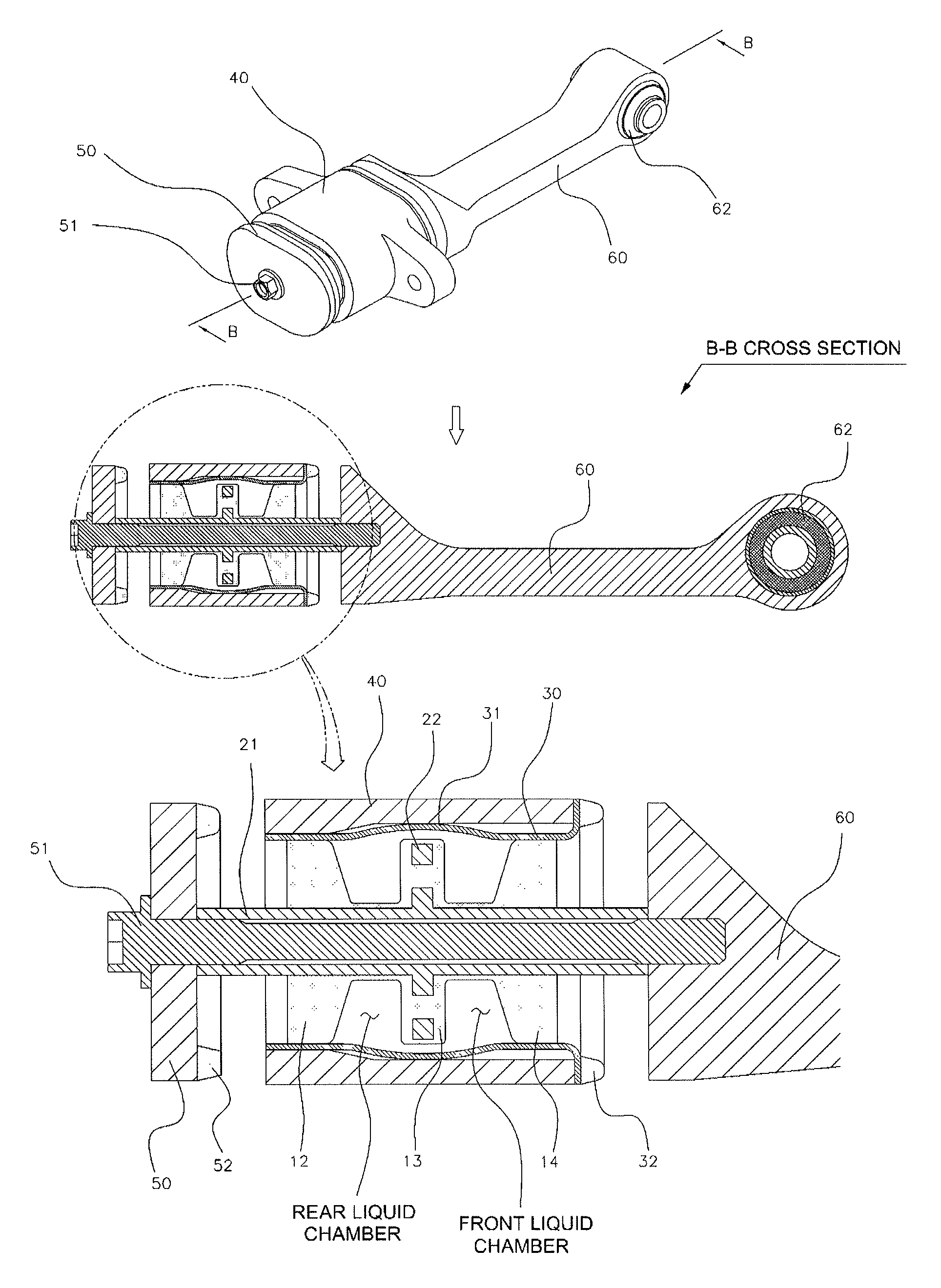
[0039]Referring to FIGS. 2 to 4, a cylindrical front bush 62 is mounted at one end of a bracket bar 60 according to the exemplary embodiment of the ...


PUM


Abstract

A structure of a roll-rod for a subframe filled with a hydro liquid therein, may include a bracket bar, an inner pipe including a cylindrical pipe and a supporting plate joined with the cylindrical pipe, an endplate joined to the cylindrical pipe, an outer pipe enclosing the inner pipe between the bracket bar and the endplate and including an extension part, where the supporting plate may be disposed with a gap in the extension part having a curved shape, an insulator forming a front liquid chamber and a rear liquid chamber with the supporting plate to receive the hydro-liquid therein, and a housing, wherein the supporting plate may move relative to the outer pipe such that the gap varies while the insulator is elastically transformed according to movement of the bracket bar and the endplate.

Description

CROSS-REFERENCE TO RELATED APPLICATIONS[0001]The present application claims priority to Korean Patent Application No. 10-2011-0082661, filed on Aug. 19, 2011, the entire contents of which is incorporated herein for all purposes by this reference.BACKGROUND OF THE INVENTION[0002]1. Field of the Invention[0003]The present invention relates to a structure of a roll-rod for a subframe, and more particularly, to a structure of a roll-rod for a subframe that can more efficiently absorb and damp impact by variably controlling a flow state of a hydro liquid depending on an applied load while alleviating vibration and supporting behavior of a power train by using flow of the hydro liquid filled therein.[0004]2. Description of Related Art[0005]A monocoque body having a small weight and high productivity is primarily used in vehicles, instead of a frame body. In the monocoque body as a structure in which an additional frame is deleted, a power train in which an engine and a transmission are jo...

Claims


Application Information

Patent Timeline
Patent Type & Authority Patents(United States)
IPC IPC(8): B60K5/12B62D21/00B60K5/00
CPCB60K5/00F16F13/1463B60K5/1208B62D21/15
Inventor KIM, SEUNG-WON
Owner HYUNDAI MOTOR CO LTD
Why Eureka
Try Eureka