
Suspension device for driving motor and electric vehicle with suspension device

A driving motor and mounting technology, applied in power units, electric power units, vehicle components, etc., can solve the problems of weak control ability of medium and high frequency vibration and noise, limited vibration absorption ability, weakened durability performance, etc. Extended range, light weight effect

Active Publication Date: 2019-03-22
SAIC GENERAL MOTORS +1
View PDF4 Cites 10 Cited by
  • Summary
  • Abstract
  • Description
  • Claims
  • Application Information

AI Technical Summary

Problems solved by technology

In order to balance the rigidity, damping and durability requirements, the suspension system of traditional internal combustion engine vehicles often has very low damping, which makes the vibration absorption capacity limited; the suspension system of traditional internal combustion engine vehicles is a single degree of freedom vibration system in a single vibration transmission direction, and the vibration isolation frequency band Narrow, and the dynamic hardening of the suspension system makes it less capable of controlling medium and high frequency vibration and noise
In addition, from the perspective of improving NVH (noise, vibration, and harshness) performance, the lower the stiffness of the suspension system, the better the NVH performance. In the case of the same size, the method of reducing the stiffness by reducing the hardness of the material impairs durability

Method used


Image

  • Suspension device for driving motor and electric vehicle with suspension device
  • Suspension device for driving motor and electric vehicle with suspension device
  • Suspension device for driving motor and electric vehicle with suspension device

Examples


Embodiment Construction

[0030] In order to make the object, technical solution and advantages of the present invention clearer, the present invention will be described in further detail below in conjunction with specific embodiments and with reference to the accompanying drawings. Wherein the same components are denoted by the same reference numerals. It should be noted that the words "front", "rear", "left", "right", "upper" and "lower" used in the following description refer to directions in the drawings. The terms "inner" and "outer" are used to refer to directions toward or away from, respectively, the geometric center of a particular component.

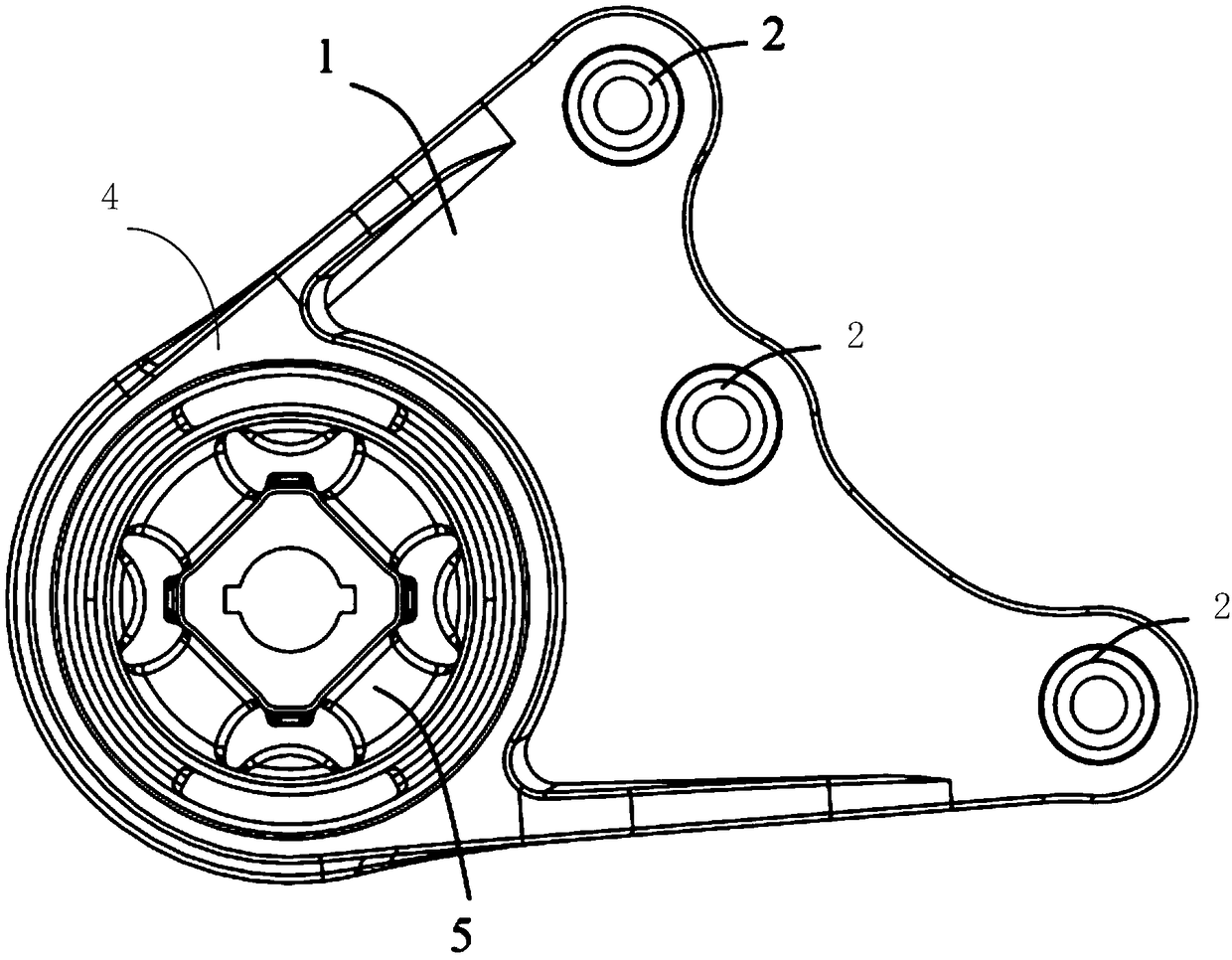
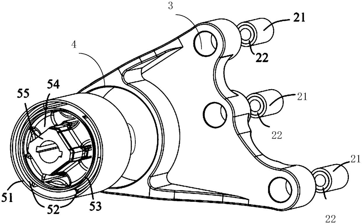
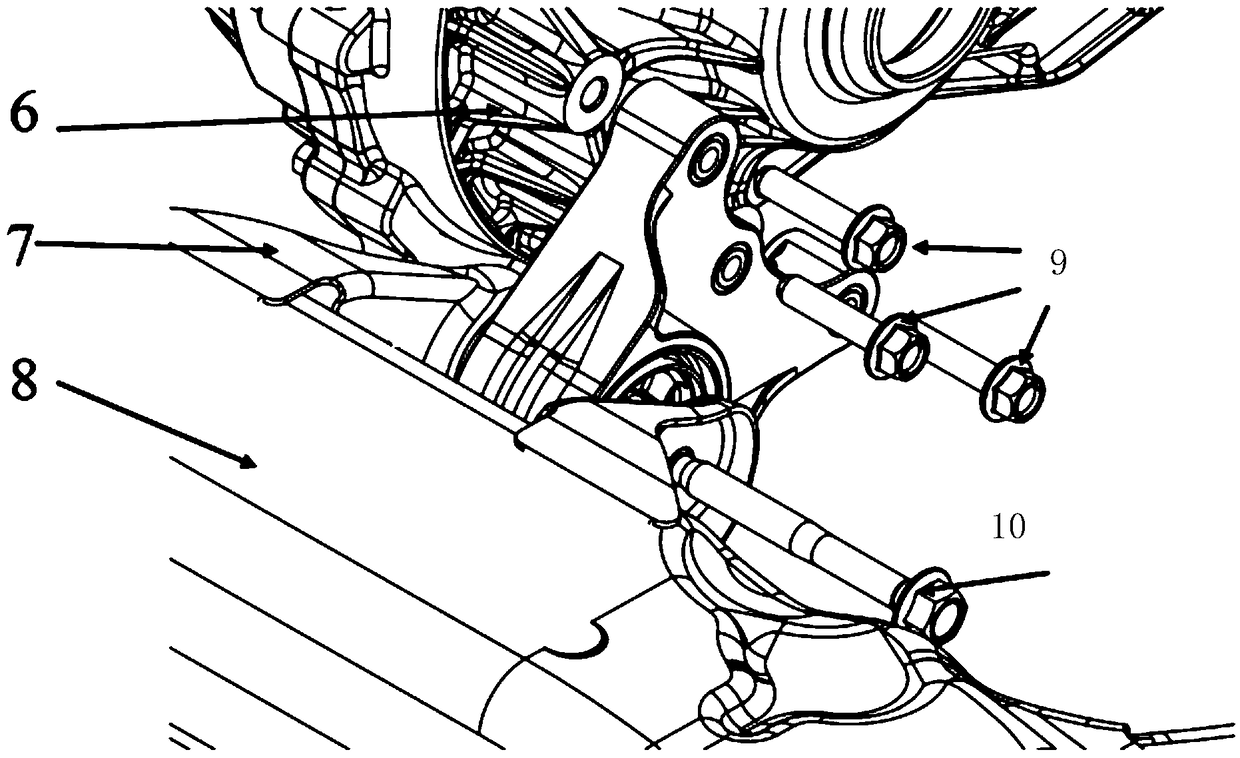
[0031] figure 1 It is a schematic diagram of a suspension device for driving a motor adopted in a specific embodiment of the present invention. figure 2 for figure 1 An exploded view of the suspension used to drive the motor is shown. image 3 for connection to the drive motor figure 1 Schematic diagram of the use state of the suspension device fo...


PUM


Abstract

The invention discloses a suspension device for a driving motor and an electric vehicle with the suspension device. The suspension device comprises a suspension body, the suspension body comprises a first end and a second end which are opposite to each other, the first end is provided with multiple through holes at intervals in the width direction, the through holes are internally provided with vibration isolation rubber bushings, and first bolts penetrate through the vibration isolation rubber bushings to fix the first end to a motor shell; the second end is provided with limiting supportingbases and screw holes, the limiting supporting bases are internally provided with vibration isolation rubber bushing assemblies, and second bolts penetrate through the vibration isolation rubber bushing assemblies and the screw holes in sequence to fix the second end to an auxiliary vehicle frame. According to the suspension device for the driving motor and the electric vehicle with the suspensiondevice, the degree of freedom is increased, the vibration isolation frequency band range is expanded, the capability of absorbing vibration is improved, the durability is improved while the overall dimension is not increased, and the requirement for NVH rigidity debugging is met.

Description

technical field [0001] The present invention relates to an automobile powertrain suspension system, more particularly, to a suspension device for driving a motor and an electric vehicle including the same. Background technique [0002] Compared with traditional internal combustion engine vehicles, the power source of new energy electric vehicles is changed from internal combustion engines to electric motors. The transformation of the drive system causes changes in the requirements for the suspension system. For example, the drive motor of electric vehicles is lighter than traditional fuel engines. , the excitation amplitude of vibration is smaller when working, and there is no idle vibration problem. [0003] When designing a suspension system suitable for electric motors, the following aspects need to be considered: First, according to the output characteristics of the electric motor, the starting torque of the electric motor is large, and high torque output can be produced...

Claims


Application Information

Patent Timeline
IPC IPC(8): B60K1/00
CPCB60K1/00
Inventor 安一领阎礁钟鸿敏黄小飞刘静静
Owner SAIC GENERAL MOTORS
Learn More