
Image-forming device and method for forming an image

a technology of image-forming device and image, which is applied in the direction of printing, other printing apparatus, etc., can solve the problems of affecting so as to improve the quality of image formation, the effect of reducing the damage to the image-forming part and other defects

Active Publication Date: 2014-09-23
SEIKO EPSON CORP
View PDF5 Cites 5 Cited by
  • Summary
  • Abstract
  • Description
  • Claims
  • Application Information

AI Technical Summary

Benefits of technology

[0010]It is therefore thought that the head portions should be retracted and contact avoided at the portions of the recording material that are curled or wrapped, but printing cannot be performed when the head portions are retracted. Useless recording material that cannot be used for printing is therefore produced, and productivity is reduced. It is also possible that a suction force sufficient to limit curling and wrapping on the suction platen should be imparted from the start, but after these portions have passed the image-forming part, imparting excessive suction force causes increased conveying load and reduced responsiveness of meander control and leads to reduced image quality.
[0019]According to the image-forming device and the method for forming an image according to the present invention, when the recording material is conveyed upon the initiation of image formation, appropriate suction characteristics are applied to the recording material that was in a released state during the stopping period, whereby the quality of image formation is improved, and damage to the image-forming part and other defects can be minimized. Images can also be formed on the portion of the recording material that was in a released state, and the usage efficiency of the recording material can therefore be improved.

Problems solved by technology

However, the recording material that is fed out in such devices may be temporarily released when the power is turned off, during printer standby, or at other times. Depending on the type of recording material, in such released states, the recording material may ruffle in the direction (the widthwise direction below) perpendicular to the conveyance direction due to moisture absorption, or the edge part may begin to curl.
Minimizing curling or wrapping tendencies using the normal suction force of a suction platen is therefore difficult, and the image that originally should have been formed at the curling or wrapping portion may be disturbed.
Contact of the heads on the recording material may disturb images even at portions that are not curled or wrapped, and such contact may damage the heads or cause other defects.
Useless recording material that cannot be used for printing is therefore produced, and productivity is reduced.
It is also possible that a suction force sufficient to limit curling and wrapping on the suction platen should be imparted from the start, but after these portions have passed the image-forming part, imparting excessive suction force causes increased conveying load and reduced responsiveness of meander control and leads to reduced image quality.

Method used


Image

  • Image-forming device and method for forming an image
  • Image-forming device and method for forming an image
  • Image-forming device and method for forming an image

Examples


Embodiment Construction

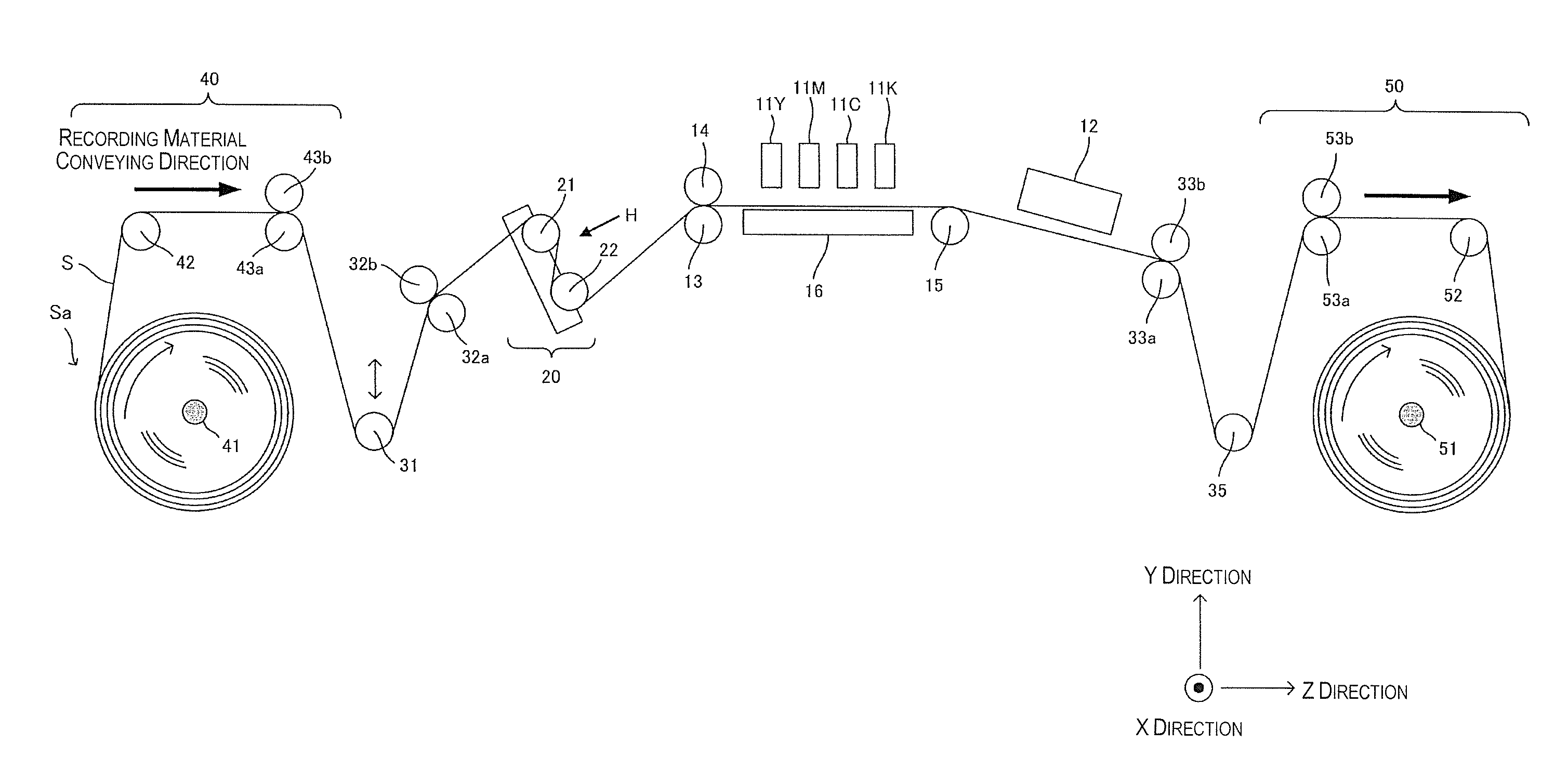
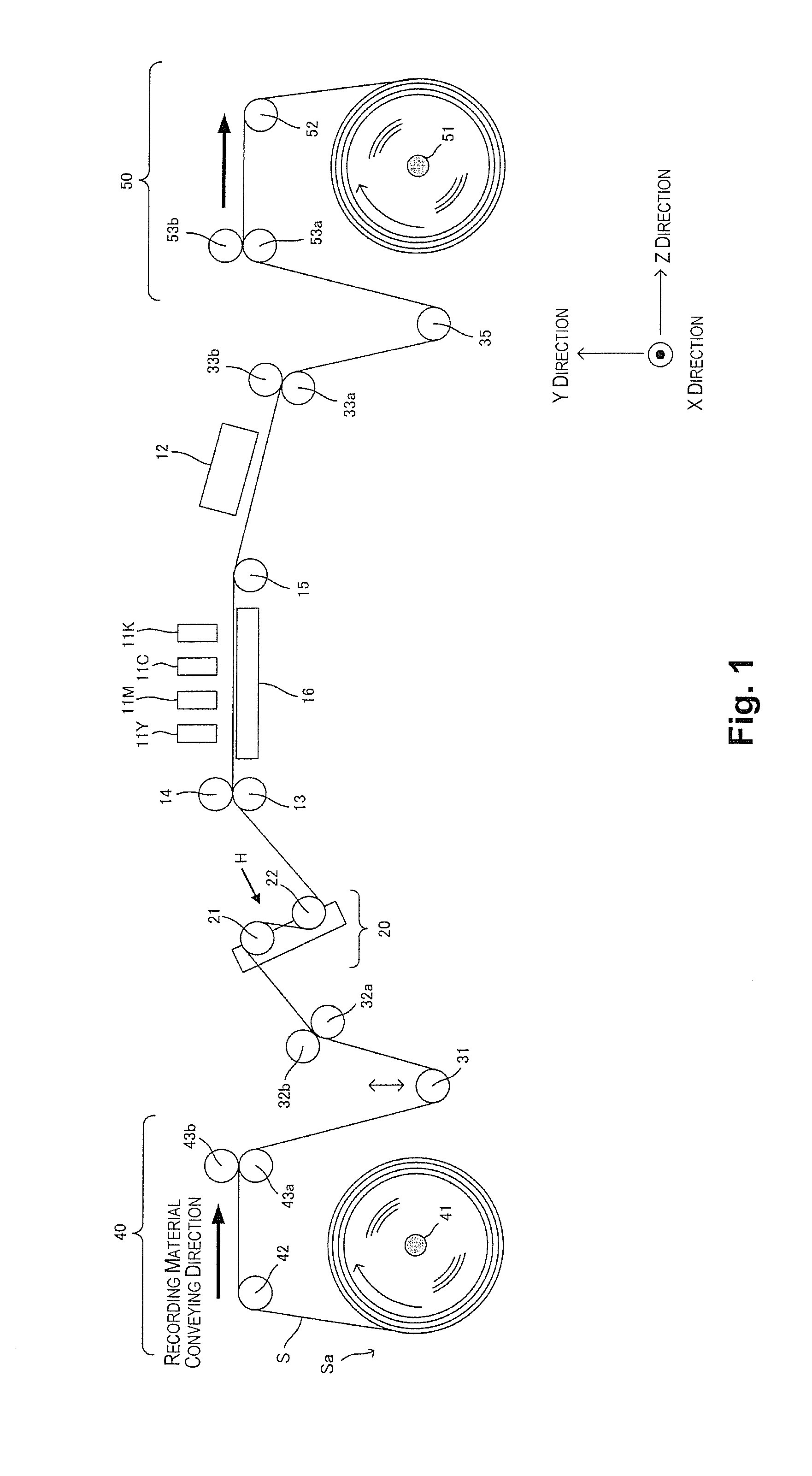
[0042]An embodiment of the present invention will be described with reference to the drawings. FIG. 1 shows the configuration of an image-forming device according to an embodiment of the present invention. The image-forming device according to the present embodiment uses photo-curing ink and is of a format involving a process in which ink is discharged from image-forming heads 11 onto a recording material S, then irradiated with light, and thereby fixed. Ultraviolet rays are employed as the light used in the present embodiment.

[0043]FIG. 1 is a lateral view of the image-forming device. As shown in FIG. 1, the direction in which the recording material S is carried is the Z direction, and the widthwise direction of the recording material S is the X direction. The primary configuration of the image-forming device includes color image-forming heads 11Y, 11M, 11C, 11K for forming (printing) pictures on the recording material S, and a conveying part comprising various rollers and the like...


PUM


Abstract

An image-forming device includes an image-forming part, a conveying part, a suction part and a control part. The image-forming part is configured and arranged to form an image on a recording material that is rolled up in a recording material roll. The conveying part is configured and arranged to feed out the recording material from the recording material roll and to convey the recording material to the image-forming part. The suction part is configured and arranged to suction the recording material conveyed by the conveying part, the suction part being disposed at the image-forming part. The control part is configured to control a suction characteristic of the suction part according to a conveyance amount of the recording material after the recording material has begun to be conveyed by the conveying part.

Description

CROSS-REFERENCE TO RELATED APPLICATIONS[0001]This application claims priority to Japanese Patent Application No. 2011-064432 filed on Mar. 23, 2011. The entire disclosure of Japanese Patent Application No. 2011-064432 is hereby incorporated herein by reference.BACKGROUND[0002]1. Technical Field[0003]The present invention relates to an image-forming device and a method for forming an image, in which an image is formed by an image-forming part on a long roll of paper or other recording material.[0004]2. Related Art[0005]Color inkjet printers of a type that discharges ink of a variety colors from image-forming heads and forms an image on printing paper or another recording material have become widespread as output devices for computers in recent years. Comparatively large color inkjet printers for using a plurality of image-forming heads to print on rolled paper or another recording material have also been implemented recently.[0006]A device is described in Japanese Laid-Open Patent Ap...

Claims


Application Information

Patent Timeline
Patent Type & Authority Patents(United States)
IPC IPC(8): B41J29/393B41J11/00B41J15/04
CPCB41J11/0085B41J11/002B41J15/04B41J11/00214
Inventor IMAMURA, ATSUSHI
Owner SEIKO EPSON CORP
Learn More